Owner’s Manual
Opto Comp Analog Optical Compressor TABLE OF CONTENTS Introduction ��������������������������������������������������������������������������������������� 2 Features ��������������������������������������������������������������������������������������������� 2 Top Panel Features ��������������������������������������������������������������������������� 3 Rear and Bottom Panel Features ����������������������������������������������������� 4 Suggested Settings ����������������������������������������������
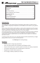
Opto Comp Analog Optical Compressor Top Panel Features Rotate the Compression knob (also known as “ratio control”) to adjust the overall amount of compression applied to a signal. 5 4 6 8 1 3 7 5. 2 Analog Optical Compressor 1. INPUT: The signal output from an instrument (active or passive) may be connected to this 1/4" input by means of an unbalanced (shielded) instrument cable. 6. NOTE: There is a –15 dB Pad Jumper [11] located inside of the pedal (see page 5). 2. 3. 4.
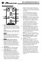
Opto Comp Analog Optical Compressor Rear and Bottom Panel Features Remove each of the four screws by turning them counter-clockwise. Be sure to keep them in a safe place as you will need them again! 9 10 POWER CONNECTOR: This is where to connect the optional power supply. J1 1 2 3 Before plugging in the power supply, make sure that you are using the correct model power supply for this product. Failure to do so may result in damage to your unit and void your warranty.
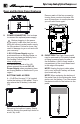
Opto Comp Analog Optical Compressor Rear and Bottom Features - Continued 11. –15 dB PAD JUMPER: Moving the jumper reduces the input signal by 15 dB and compensates for higher output instruments. This attenuation is suited for use with basses that have active electronics or high-output pickups. There are only two possibilities for the jumper setting: • Pins 1-2 (Normal – default) • Pins 2-3 (15 dB Pad) Ok, ok...
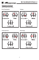
Opto Comp Analog Optical Compressor Suggested Settings Set the Output Level to taste.
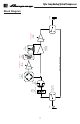
INPUT HEAVY-DUTY FOOTSWITCH INPUT SIGNAL PAD (O dB / –15 dB) HI-Z JFET BUFFER AC-TO-DC LEVEL DETECTOR RELEASE TIME CONTROL TRUE-BYPASS SWITCHING PATH COMPRESSION RATIO CONTROL GAIN REDUCTION AMPLIFIER OPTO ISOLATOR OUTPUT LEVEL GAIN CONTROL OUTPUT Opto Comp Analog Optical Compressor Block Diagram 7
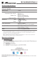
Opto Comp Analog Optical Compressor Technical Specifications Signal-to-Noise Ratio (100 Hz @ 1.00V RMS) 80 dB Maximum Gain +14 dB Controls Compression Ratio, dB (I/O) Minimum: 1:1 Maximum: 10:1 Release Time Minimum: 75 milliseconds Maximum: 600 milliseconds Output Level Gain Mute to +14 dB Impedances Input Output 1 M @ NORMAL, 166 k w/–15 dB PAD 200 Power Requirements Internal: 9V Battery External: 9V DC, ≥25 mA, center negative Size (H x W x D) 2.2 in x 2.6 in x 4.