
User Manual

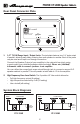
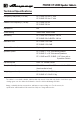
Table Of Contents

2
PF-115HE / PF-210HE Speaker Cabinets
What’s in the Box
PF-115HE or PF-210HE Speaker Cabinet, Speaker Cable, Quick Start Guide.
Introduction
Portable. Powerful. Sexy. Ampeg designed and built the original Portaex
®
Series
products over 50 years ago. Congratulations are in order—for today, in your hands, is the
new-and-improved Portaex!
Featuring a high frequency horn with 3-position switch, four removable casters, a stylish
top handle, and black, diamond pattern tolex, these Eminence
®
speaker loaded cabinets
can handle up to 450W of power!
Don’t stop now! Your Portaex cabinet is an ideal companion to the Ampeg PF-350 or
Ampeg PF-500 amplier, available separately.
Like all Ampeg products, your Portaex cabinet is designed by musicians and built
using only the best of components. Each cabinet is tested to conrm that it meets our
specications, and we believe that this cabinet is the absolute best that it can be.
In order to get the most out of your new cabinet, please fully read this Owner's Manual, as
well as the Important Safety Instructions packed with your product before you begin playing.
And thank you for choosing Ampeg.
Features
• Designed to stack with a Portaex amplier (available separately)
• Aligned screw holes and clasps allow secure stacking of a Portaex amplier
• Loaded with Eminence speaker(s) for high quality sound
• Equipped with a high frequency horn and a 3-position switch
• Two paralleled 1/4" TS Input and Output jacks
• Nominal impedance: 8 Ω
• Power handling: 450W RMS
• Four removable casters
• Stylish top handle and black, diamond pattern tolex
• Flip-top functionality allows for compact and secure transport of cabinet and
Portaex head (available separately)
TABLE OF CONTENTS
What’s in the Box . . . . . . . . . . . . . . . . . . . . . . . . . . . . . . . . . . . 2
Introduction
. . . . . . . . . . . . . . . . . . . . . . . . . . . . . . . . . . . . . . . . 2
Features
. . . . . . . . . . . . . . . . . . . . . . . . . . . . . . . . . . . . . . . . . . . 2
Rear Panel Connector Plate
. . . . . . . . . . . . . . . . . . . . . . . . . . . 3
System Block Diagrams
. . . . . . . . . . . . . . . . . . . . . . . . . . . . . . 3
Technical Specications
. . . . . . . . . . . . . . . . . . . . . . . . . . . . . . 4
Warranty and Support
. . . . . . . . . . . . . . . . . . . . . . . . . . . . . . . . 5