
User Manual

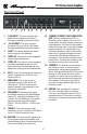
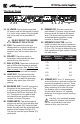
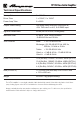
Table Of Contents

3
SVT-CL Bass Guitar Amplifier
The Front Panel
1 2 3 4 5 6 7 8 9 10 11 12 13
1. 0 dB INPUT: This jack accepts the
signal from a passive instrument
through a shielded instrument cable.
2. -15 dB INPUT: This jack accepts
the signal from an active instrument
through a shielded instrument cable.
3. GAIN: This control adjusts the basic
level of signal in the preamp.
4. ULTRA HI: This switch, when engaged,
boosts high frequencies.
5. ULTRA LO: This switch, when engaged,
provides emphasis to the low end
by boosting the low frequencies and
selectively cutting the mid frequencies.
6. BASS: This is the primary low frequency
control. It allows for 12 dB of cut or
boost at 40 Hz.
7. MIDRANGE: This is the primary
midrange control. It allows for 20
dB of cut or 10 dB of boost at the
center frequency, as selected by the
Frequency control [8].
8. FREQUENCY: Allows you to select
the center frequency for the Midrange
control [7], providing a choice of ve
“voices” for the Midrange. The center
frequencies are (from left to right)
220 Hz, 450 Hz, 800 Hz, 1.6 kHz, and
3 kHz.
9. TREBLE: This is the primary high
frequency control. It allows for 20 dB of
cut or 15 dB of boost at 4 kHz.
10. MASTER: This controls the signal level
to the power amp and, therefore, the
overall listening level. It also controls the
level to the Preamp Out jack [21].
11. STANDBY/POWER/FAULT INDICATOR
LED: This is a multifunction LED. In
Standby mode, it glows red. In the On
mode (when the high voltage comes on)
it glows green. If it does not turn green
in the On mode, there is no high voltage
present and the unit needs servicing.
If the amp detects a fault in the power
tube circuit, the high voltage is turned
o and the LED ashes between red
and green. This usually indicates a bad
power tube. The amp will remain in this
condition until the unit is turned o.
12. STANDBY: The Standby mode allows
the tubes to warm, or remain warm,
without high voltage being applied to
them. This extends tube life. This switch
should be OFF when rst turning the
amplier on. Allow the unit to warm up
for 20 seconds before switching to the
ON position. During short periods of
non-use, the amp should be put into
Standby mode.
13. POWER: This supplies AC power to
the unit. Turn this switch on before
turning on the Standby switch [12], as
explained above. This switch must be
turned o to reset the amp after a fault
condition.