SURVEYING INSTRUMENTS INSTRUCTION MANUAL Onboard Station OS series OS-101 OS-102 OS-103 OS-105 OS-107 21406 99020
Li-ion S Li-ion This is the mark of the Japan Surveying Instruments Manufacturers Association.
SURVEYING INSTRUMENTS OS series Class 3R Laser Product INSTRUCTION MANUAL • Thank you for selecting the OS-101/102/103/105/107. • Please read this instruction manual carefully, before using this product. • OS has a function to output data to a connected host computer. Command operations from a host computer can also be performed. For details, refer to "Communication manual" and ask your local dealer.
HOW TO READ THIS MANUAL Symbols The following conventions are used in this manual. G : Indicates precautions and important items which should be read before operations. C : Indicates the chapter title to refer to for additional information. $ : Indicates supplementary explanation. & : Indicates an explanation for a particular term or operation. [Softkey] etc. : Indicates softkeys on the display and window dialog buttons. {Key} etc. : Indicates keys on the operation panel.
HOW TO READ THIS MANUAL • • • • KODAK is a registered trademark of Eastman Kodak Company. ® Bluetooth is a registered trademark of Bluetooth SIG, Inc. Windows and Windows CE are registered trademarks of Microsoft Corporation. All other company and product names featured in this manual are trademarks or registered trademarks of each respective organization.
CONTENTS 1. PRECAUTIONS FOR SAFE OPERATION......................... 1 2. PRECAUTIONS .................................................................. 4 3. LASER SAFETY INFORMATION ....................................... 8 4. PRODUCT OUTLINE........................................................ 10 4.1 4.2 4.3 Parts of the Instrument .............................................................. 10 Mode Structure ..........................................................................
13. DISTANCE MEASUREMENT........................................... 54 13.1 13.2 13.3 13.4 Returned Signal Checking ........................................................ 54 Distance and Angle Measurement ............................................ 56 Distance Measurement and Outputting the Data ...................... 57 REM Measurement ................................................................... 58 14. COORDINATE MEASUREMENT..................................... 60 14.1 14.2 14.
20.11 Date and Time ......................................................................... 124 21. WARNING AND ERROR MESSAGES........................... 125 22. CHECKS AND ADJUSTMENTS..................................... 129 22.1 22.2 22.3 22.4 22.5 22.6 22.7 Circular Level .......................................................................... 129 Tilt Sensor ............................................................................... 130 Collimation .............................................
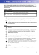
1. PRECAUTIONS FOR SAFE OPERATION For the safe use of the product and prevention of injury to operators and other persons as well as prevention of property damage, items which should be observed are indicated by an exclamation point within a triangle used with WARNING and CAUTION statements in this operator’s manual. The definitions of the indications are listed below. Be sure you understand them before reading the manual’s main text.
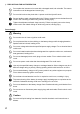
1. PRECAUTIONS FOR SAFE OPERATION D Do not place the instrument in a case with a damaged catch, belt or handle. The case or instrument could be dropped and cause injury. D Do not wield or throw the plumb bob. A person could be injured if struck. E Secure handle to main unit with handle locks. Failure to properly secure the handle could result in the unit falling off while being carried, causing injury. E Tighten the adjustment tribrach clamp securely.
1. PRECAUTIONS FOR SAFE OPERATION Tripod C Caution E When mounting the instrument to the tripod, tighten the centering screw securely. Failure to tighten the screw properly could result in the instrument falling off the tripod, causing injury. E Tighten securely the leg fixing screws of the tripod on which the instrument is mounted. Failure to tighten the screws could result in the tripod collapsing, causing injury. D Do not carry the tripod with the tripod shoes pointed at other persons.
2. PRECAUTIONS Telescope • Aiming the telescope at the sun will cause internal damage to the instrument. Use the solar filter when observing the sun. C"25. Optional accessories" Tribrach Clamp and Handle • When the instrument is shipped, the tribrach clamp is held firmly in place with a locking screw to prevent the instrument from shifting on the levelling base. Before using the instrument the first time, loosen this screw with a screwdriver.
2. PRECAUTIONS Vertical and horizontal clamps • Always fully release the vertical/horizontal clamps when rotating the instrument or telescope. Rotationg with clamp(s) partially applied may adversely affect accuracy. Backing up data • Data should be backed up (transferred to an external device etc.) on a regular basis to prevent data loss. Use under low temperatures (Low Temperature Model only) • Do not use force to scrape off frost from the lens or display unit screen.
2. PRECAUTIONS Exporting this product • This product is equipped with the parts/units, and contains software/technology, which are subject to the EAR (Export Administration Regulations). Depending on countries you wish to export or bring the product to, a US export license may be required. In such a case, it is your responsibility to obtain the license. The countries requiring the license as of January 2012 are shown below. Please consult the Export Administration Regulations as they are subject to change.
2. PRECAUTIONS Exceptions from responsibility • The user of this product is expected to follow all operating instructions and make periodic checks (hardware only) of the product’s performance. • The manufacturer, or its representatives, assumes no responsibility for results of faulty or intentional usage or misuse including any direct, indirect, consequential damage, or loss of profits.
3. LASER SAFETY INFORMATION OS is classified as the following class of Laser Product according to IEC Standard Publication 608251 Ed.2.0: 2007 and United States Government Code of Federal Regulation FDA CDRH 21CFR Part 1040.10 and 1040.11 (Complies with FDA performance standards for laser products except for deviations pursuant to Laser Notice No.50, dated June 24, 2007.
3. LASER SAFETY INFORMATION CCaution • Perform checks at start of work and periodic checks and adjustments with the laser beam emitted under normal conditions. • When the instrument is not being used, turn off the power and replace the lens cap. • When disposing of the instrument, destroy the battery connector so that the laser beam cannot be emitted. • Operate the instrument with due caution to avoid injuries that may be caused by the laser beam unintentionally striking a person in the eye.
4. PRODUCT OUTLINE 4.1 Parts of the Instrument Parts and functions of the instrument 18 17 16 4 15 1 14 4 2 5 6 7A 8 12 11 9 10 29 28 19 20 27 26 4 4 21 22 23 15 24 25 OS-101/102 and low temperature models only 7B Handle Bluetooth antenna External interface hatch (USB port / Reset button) 3 13 10 1 2 3 4 5 6 7A 7B 8 9 10 11 12 13 14 15 16 17 18 19 20 21 22 23 24 25 26 27 28 29 C"10.
4. PRODUCT OUTLINE & Guide light Setting-out measurement etc. can be carried out effectively using the guide light. The guide light is composed of a light that is divided into green and red sections. A poleman can ascertain the present position by checking the guide light color.
4. PRODUCT OUTLINE Bluetooth antenna (Models with Bluetooth module only) The Bluetooth antenna allows communication via Bluetooth wireless technology. G • Handle the antenna with care. The antenna may be damaged if struck during operation or while being stored in the carrying case. Handle The carrying handle can be removed from the instrument. To remove it, loosen the handle rocking screw. G • To remove the handle, hold both sides of the handle and lift it straight above.
4. PRODUCT OUTLINE 4.2 Mode Structure The diagram below describes the different modes of the OS and key operations for navigating between them. ●Basic mode Observation mode (switching by tab) Top menu C “5.2 Display Functions ٨”Graphic“ tab” Menu mode ÛVersionÝ =OK? ]ESC_ ]_ڎ C“12. to 19” Config mode C“20.Changing the settings” ]PRG_ ●Star key mode ●Program mode C“5.4 Star key mode” ]_ڎ G • Switching between modes is not possible during distance measurement.
4. PRODUCT OUTLINE 4.3 Bluetooth Wireless Technology G • Bluetooth communication is only possible with instruments incorporating the Bluetooth module. • Use of this technology must be authorized according to telecommunications regulations of the country where the instrument is being used. Contact your local dealer in advance. C"28. REGULATIONS" • TOPCON CORPORATION is not liable for the content of any transmission nor any content related thereto.
4. PRODUCT OUTLINE • Televisions and radios use a different frequency band to Bluetooth communications. However, even if the OS is used within proximity to the above equipment with no adverse effects with regard to Bluetooth communication, moving a Bluetooth compatible device (including the OS) closer to said equipment may result in electronic noise in sound or images, adversely affecting the performance of televisions and radios.
5. BASIC OPERATION Learn basic key operations here before you read each measurement procedure. 5.
5. BASIC OPERATION I Switching the page {FUNC} I Inputting letters/figures {α } Switch between numerals and alphabetic characters {SHIFT} + {1} to {9} In alphabetic characters mode, switch between lowercase characters and upper case characters each time In alphabetic characters mode, switch between lowercase characters and upper case characters {SHIFT} (Press and hold) {α} + {SHIFT} {0} to {9} {.} {± } {ESC} {TAB} {B.S.} {S.P.
5. BASIC OPERATION Example: Entering "computer" (lower case) as the name of a new device 1. Tap the input mode icon in the status bar (second from bottom) until "_a" is displayed. 2. Press {7} three times. "c" is displayed. P1 3. Press {5} three times. "o" is displayed.
5. BASIC OPERATION 4. Press {L}. Press {5}. "m" is displayed. 5. Continue to input letters. Press {ENT} to complete inputting. Example: selecting a reflector type (Method 1) 1. Select [EDM] in the first page of Observation mode or "EDM" in Config mode/Configuration mode. CI Observation mode screen (P.22) 2. Move to "Reflector" using {O}/{G}/{TAB}. 3. Press {SPACE} to display a list of all options. 4. Select an option using {O}/{G}. 5. Press {ENT} to confirm selection.
5. BASIC OPERATION (Method 2) 1. Select [EDM] in the first page of Measure mode or "EDM" in Config mode/Configuration mode. 2. Move to "Reflector" using {O}/{G}/{TAB}. 3. Switch between Prism, Sheet, and N-Prism using {K}/{L}. 4. Press {ENT} to confirm selection. 5.2 Display Functions Screens can be selected/operated using the keys on the keyboard or the touch panel. The touch panel can be operated using either the stylus pen provided or your fingers.
5. BASIC OPERATION Temporarily de-activating the touch panel The touch panel can be temporarily de-activated. This is especially useful when cleaning the display. To de-activate, tap on the status bar. is displayed. The touch panel cannot be operated while the above message is displayed. Press {ESC} to cancel the message and re-activate the touch panel. • Touch panel icon C"20.7 Changing Status Bar Icons" : Touch panel temporarily de-activated.
5. BASIC OPERATION Displaying and operating screens • To close a screen, tap the cross in the top right corner, or press {ESC}. • Tabs, softkey allocations, displayed tab items, and character sizes can all be changed in accordance with user preferences. C"20.
5. BASIC OPERATION (3) Horizontal angle Press [R/L] when allocated to the Observation mode screen to switch the display status. The capitalized letter in the softkey indicates the currently selected mode. HA-R : Horizontal angle right HA-L : Horizontal angle left C "20.
5. BASIC OPERATION I Selecting menus To select a menu, tap the touch panel or press the relevant number key. Number I Status bar Indicates the current status of the instrument. Tapping icons (1) to (8) will switch between the relevant options for that item. Tapping and holding will display a list of all available options for that item and, in certain cases, a link to the configuration screen for that item. CSettings: "20.
5. BASIC OPERATION When using external battery : Level 3 Full power : Level 2 Plenty of power remains : Level 1 Half or less power remains Level 0 Little power remains. Prepare a replacement battery where available C"7. USING THE BATTERY" (2) Target display Selection of target type and configuration of prism constant. : Prism (0mm) : Sheet (0mm) : N-Prism Target information can be edited/recorded in . C"20.3 EDM Settings" (3) PPM setting Configuration of EDM.
5. BASIC OPERATION (5) Tilt angle compensation The vertical and horizontal angles are automatically compensated for small tilt errors using the OS's dual-axis tilt sensor. This icon displays the status of this function. : Horizontal and vertical tilt angles compensated (blue) : No compensation : Only vertical tilt angle compensated (green) $ • is displayed when the instrument is out of level.
5. BASIC OPERATION ii) : Connection via RS232C cable $ • An arrow (e.g. / ) is displayed to indicate that data transmission is in progress. A red arrow indicates that data transmission has failed and data needs to be sent again.
5. BASIC OPERATION 5.3 Disk Capacity Disk usage of the instrument is displayed as follows. Tap and hold disk icon in the status bar to check the detail of the disk usage. C"20.
5. BASIC OPERATION 5.4 Inputting Characters using the Input Panel Tap or press {α} and {SHIFT} to display . This keyboard can be used to input numeric and alphabetic characters as well as symbols. Tap the icon again to close. $ • When is covering the icon of the status bar, use the stylus pen to drag the input panel to another part of the screen so that you can access the icon.
6. INSERTING USB MEMORY G • When reading/writing data, do not remove the USB memory. Procedure 1. Open the external interface hatch by sliding its button. External interface hatch 2. Insert the USB memory into the USB port 1. USB Port 1 G • When using a USB memory with 4 metal terminals on the surface, insert it with the terminal facing backwards to avoid damaging the USB port. USB Port 2 3. Close the external interface hatch until a click is heard.
7. USING THE BATTERY C Types of power source: "23. POWER SUPPLY SYSTEM" 7.1 Battery Charging The battery was not charged at the factory. Charge the battery fully before using the OS. G • • • • The charger will become rather hot during use. This is normal. Do not use to charge batteries other than those specified. The charger is for indoor use only. Do not use outdoors. Batteries cannot be charged, even when the charging lamp is flashing, when the temperature is outside the charging temperature range.
7. USING THE BATTERY 3. When charging starts, the lamp starts blinking. 4. The lamp lights when charging is finished. 5. Remove the battery and unplug the charger. $ • Slots 1 and 2: The charger starts charging the battery mounted first. If you place two batteries in the charger, the battery in slot 1 is charged first, and then the battery in slot 2. (C step 2) • Charging lamp: The charging lamp is off when the charger is outside the charging temperature range or when the battery is mounted incorrectly.
7. USING THE BATTERY PROCEDURE Mounting the battery 1. Slide down the catches on the battery cover to open. Battery cover 2. Insert the battery in the direction of the arrow on the side of the battery. G • Do not insert the battery inclined. Doing so may damage the instrument or battery terminals. 3. Close the battery cover. A click is heard when the cover is secure.
8. SETTING UP THE INSTRUMENT G • Mount the battery in the instrument before performing this operation because the instrument will tilt slightly if the battery is mounted after levelling. 8.1 Centering PROCEDURE Centering with the optical plummet eyepiece 1. Make sure the legs are spaced at equal intervals and the head is approximately level. Set the tripod so that the head is positioned over the survey point. Make sure the tripod shoes are firmly fixed in the ground. 2.
8. SETTING UP THE INSTRUMENT PROCEDURE Centering with the laser plummet (Option) 1. Set up the tripod and affix the instrument on the tripod head. C"8.1 Centering" 2. Press {ON} to power on C"9. POWER ON/OFF" The electric circular level (tilt) is displayed on the screen. 3. Press [L-ON]. The laser plummet beam will be emitted from the bottom of the instrument. 4. Use [-]/[+] on the second page to adjust the brightness of the laser. 5.
8. SETTING UP THE INSTRUMENT $ • Visibility of the laser spot may be affected when operating in direct sunlight. In this event, provide shade for the survey point. 8.2 Levelling Instrument can be levelled using the screen. C“$ Levelling on the screen” PROCEDURE 1. Adjust the levelling foot screws to center the survey point in the optical plummet reticle. 2.
8. SETTING UP THE INSTRUMENT 5. Turn the instrument until the telescope is parallel to a line between levelling foot screws A and B. 6. Set the tilt angle to 0° using foot screws A and B for the X direction and levelling screw C for the Y direction. 7. Loosen the centering screw slightly. Looking through the optical plummet eyepiece, slide the instrument over the tripod head until the survey point is exactly centered in the reticle. Retighten the centering screw securely.
9. POWER ON/OFF PROCEDURE Power ON 1. Press { }. When the power is switched on, the Tilt screen is displayed. Press {ESC} to go to top menu. If "Out of range" is displayed, the instrument tilt sensor is indicating that the instrument is out of level. Level the instrument once again using circular level, then the tilt screen will be displayed. $ • "Tilt crn." in "Obs. condition" should be set to "No" if the display is unsteady due to vibration or strong wind. C "20.
9. POWER ON/OFF 9.1 Configuring the Touch Panel When using for the first time, or after performing a cold boot, the screen for configuring the touch panel will be displayed. Follow the instructions on the screen. Tap the crosshairs at the center of the display with the stylus pen. Tap 5 times. Press {ENT} to complete touch panel configuration. Press {ESC} to retain previous settings. $ • Touch panel configuration can be performed at any time during normal operation by pressing [PNL CAL] in
9. POWER ON/OFF & Problems Powering OFF When the instrument cannot be powered OFF as normal, depress the reset button with the tip of the stylus pen. • Pressing the Reset button may result in file and folder data being lost.
10.CONNECTING TO EXTERNAL DEVICES The OS supports Bluetooth wireless technology, USB and RS232C for communication with data collectors etc. Read this manual in conjunction with the operator’s manual for the relevant external device. C Bluetooth communication: "4.3 Bluetooth Wireless Technology" Output format and command operations: "Communication manual" G • Bluetooth communication is only possible with instruments incorporating the Bluetooth module. 10.
10. CONNECTING TO EXTERNAL DEVICES Off: Omit the [ACK] $ • Setting ’(3) and (4) are for an instrument using GTS commands. 2. Select a mode for the OS in the "Bluetooth" tab. The factory setting is "Slave". Register companion devices. • "Master" cannot be selected when no companion devices have been registered. C "Master"/"Slave": "& Bluetooth connections" 3. Select, in "Link", a companion device from among the Bluetooth devices already registered in the OS.
10. CONNECTING TO EXTERNAL DEVICES PROCEDURE Registering Bluetooth companion devices 1. Power on the companion device. 2. Select "Bluetooth" in "Comms mode" in the "Comms setup" tab. 3. Press [LIST] to display a list of all registered devices. Register the data collectors to use in "Serial" tab and devices to use with the Dial-Up Program in "Dial-up" tab. G • Maximum number of devices registered: 6 4. Register your Bluetooth device(s). Press [Add] to display .
10. CONNECTING TO EXTERNAL DEVICES Press [Search] to search about Bluetooth devices in the immediate vicinity of the OS and display their device name and address in a list. Select a device from this list and press [OK] to add to the Link device list in step 3. Press [Delete] to delete the selected device name. Deleted device names cannot be retrieved. • Select a device and press [Edit] in the second page to update the device name and/or device address. 5.
10. CONNECTING TO EXTERNAL DEVICES 10.2 Communication between the OS and Companion Device G • Bluetooth communication causes OS battery power to be depleted at a rate higher than that for normal operation. • Check that the companion device (data collector, computer, or cellular phone etc.) is turned on and the relevant Bluetooth settings are complete. • All communication settings will be changed to factory settings when a cold boot is performed. Comms setup will need to be performed again. C"10.
10. CONNECTING TO EXTERNAL DEVICES 10.3 Connecting to USB devices OS has two different USB ports. TOPCON CORPORATION cannot guarantee that all USB devices are compatible with the OS USB ports. G • TOPCON CORPORATION cannot guarantee that all USB devices are compatible with the OS USB ports. • Use a computer WindowsXP/Vista/7 is based and USB connection is capable. USB port 1 USB port 2 Each port is used for connection to different types of devices.
10. CONNECTING TO EXTERNAL DEVICES 1. Power OFF the OS. Connect the OS and computer using the USB cable. C "9. POWER ON/OFF" $ • The computer does not need to be turned OFF before connection. 2. Press { } while pressing {ENT} to dislay a message box asking whether to boot USB mode, then press [YES]. The screen of the instrument will be . $ • OS may not be displayed as . It depends on Windows settings.
10. CONNECTING TO EXTERNAL DEVICES 2. Press { } while pressing {ENT} to dislay a message box asking whether to boot USB mode, then press [NO]. The synchronous software is effective. $ • OS may not be displayed as . It depends on Windows settings. G Follow the instructions below to ensure that the OS continues to operate normally during USB transfer. • Do not change the folder hierarchy or folder names in . • Do not format the "removable disk" on the computer. 3.
10. CONNECTING TO EXTERNAL DEVICES 10.4 Connection via RS232C cable PROCEDURE Basic cable settings 1. Connect the cable. C Cables: "25. OPTIONAL ACCESSORIES" 2. Select "Comms" in Config mode. Set communication conditions in the "Comms setup" tab. Set "Comms mode" to "RS232C". 3. Set options in the "RS232C" tab according to the selection made in the "Comms setup" tab.
11.FOCUSSING AND TARGET SIGHTING G • When sighting the target, strong light shining directly into the objective lens may cause the instrument to malfunction. Protect the objective lens from direct light by attaching the lens hood. Observe to the same point of the reticle when the telescope face is changed. PROCEDURE 1. Focus on the reticle Look through the telescope eyepiece at a bright and featureless background.
12.ANGLE MEASUREMENT This section explains the procedures for basic angle measurement in Observation mode. • It is possible to allocate softkeys in measurement menus to suit various applications and the ways that different operators handle the instrument. C"20.6 Allocating Key Functions" 12.1 Measuring the Horizontal Angle between Two Points (Horizontal Angle 0°) Use the “0SET” function to measure the included angle between two points. The horizontal angle can be set to 0 at any direction. PROCEDURE 1.
12. ANGLE MEASUREMENT 12.2 Setting the Horizontal Angle to a Required Value (Horizontal Angle Hold) You can reset the horizontal angle to a required value and use this value to find the horizontal angle of a new target. PROCEDURE 1. Sight the first target. 2. In the second page of Observation mode, press [H-SET]. is displayed. 3. Enter the angle you wish to set, then press [OK]. The value that is input as the horizontal angle is displayed.
12. ANGLE MEASUREMENT 12.3 Angle measurement and Outputting the Data The following explains angle measurement and the features used to output measurement results to a computer or other external devices. C"10. CONNECTING TO EXTERNAL DEVICES", Cables: "25. OPTIONAL ACCESSORIES", Output format and command operations: "Communication manual" PROCEDURE 1. Connect OS and external device. 2. Allocate the [HVOUT-T] or [HVOUT-S] softkey to the OBS mode screen. C"20.
13.DISTANCE MEASUREMENT Perform the following settings as preparation for distance measurement in Observation mode. • Distance measurement mode • Target type • Prism constant correction value • ppm • EDM ALC C"20.2 Instrument Configuration" • It is possible to allocate softkeys in measurement menus to suit various applications and the ways that different operators handle the instrument. C"20.
13. DISTANCE MEASUREMENT PROCEDURE 1. Accurately sight the target. 2. Press [S-LEV] in observation mode. is displayed. CAllocating [S-LEV]: "20.6 Allocating Key Functions" When [S-LEV] is pressed, a gauge indicating light intensity is displayed. • The more displayed, the greater the quantity of reflected light. • If “I” is displayed, only enough light for the measurement is returned. • When “I” is not displayed, accurately resight the target.
13. DISTANCE MEASUREMENT 13.2 Distance and Angle Measurement An angle can be measured at the same time as distance. PROCEDURE 1. Face the OS in the direction of the target Use the sighting collimator to aim the OS and telescope toward the target. C"11. FOCUSSING AND TARGET SIGHTING" 2. Start measurement. Press [MEAS] in the first page of Observation mode to start measurement. The measured distance data (SD), vertical angle (ZA), and horizontal angle (HA-R) are displayed. 3.
13. DISTANCE MEASUREMENT 13.3 Distance Measurement and Outputting the Data The following explains distance measurement and the features used to output measurement data to a computer or external devices. C"10. CONNECTING TO EXTERNAL DEVICES", Communication cables: "25. OPTIONAL ACCESSORIES". Output format and command operations: "Communication manual" PROCEDURE 1. Connect OS and external device. 2. Sight the target point. 3.
13. DISTANCE MEASUREMENT 13.4 REM Measurement An REM measurement is a function used to measure the height to a point where a target cannot be directly installed such as power lines, overhead cables and bridges, etc. The height of the target is calculated using the following formula. Ht = h1 + h2 h2 = S sin z1 x cot z2 - S cos z1 Zenith Zenith • It is possible to allocate softkeys in measurement menus to suit various applications and the ways that different operators handle the instrument. C"20.
13. DISTANCE MEASUREMENT 3. Sight the target and press [MEAS] to start measurement. Press [STOP] to stop the measurement. The measured distance data, vertical angle and horizontal angle are displayed. 4. Sight the object, then press [REM] to start REM measurement is started. The height from the ground to the object is displayed in "Ht.". Press [STOP] to stop the measurement. • To re-observe the target, sight the target then press [MEAS]. • To continue REM measurement, press [REM].
14.COORDINATE MEASUREMENT By performing coordinate measurements it is possible to find the 3-dimensional coordinates of the target based on station point coordinates, instrument height, target height, and azimuth angles of the backsight station which are entered in advance. • It is possible to allocate softkeys in measurement menus to suit various applications and the ways that different operators handle the instrument. C"20.6 Allocating Key Functions" 14.
14. COORDINATE MEASUREMENT 3. Select "Occupy setup" and enter instrument station coordinates,instrument height (HI) and target height (HR). 4. Press [OK] to set the input values. is displayed again. 14.2 Azimuth Angle Setting Based on the instrument station coordinates and backsight station coordinates which have already been set, the azimuth angle of the backsight station is calculated.
14. COORDINATE MEASUREMENT PROCEDURE Entering coordinates 1. Select "Backsight setup" in . is displayed. • can also be displayed from the screen in step 4 of "14.1 Entering Instrument Station Data". 2. Select the "Key in coord" tab and enter the backsight station coordinates. • [Azimuth]: Switches horizontal angle setting method. C "D Horizontal angle settings" • Sight the backsight station and press [MEAS].
14. COORDINATE MEASUREMENT PROCEDURE Entering angle 1. Select "Backsight setup" in . is displayed. . can also be displayed from the screen in step 4 of "14.1 Entering Instrument Station Data". 2. Select the "Key in angle" tab and enter the desired angle in "H.ang". 3. Press [OK] to set the input values. is displayed. PROCEDURE Entering azimuth 1. Select "Backsight setup" in . is displayed. .
14. COORDINATE MEASUREMENT 3. Press [OK] to set the input values. is displayed. & Horizontal angle settings Azimuth (set both horizontal and azimuth angles to the same value)/H.ang (input both horizontal and azimuth angles)/None (input azimuth angle only)/0 SET (horizontal angle set to 0°) 14.3 3-D Coordinate Measurement The coordinate values of the target can be found by measuring the target based on the settings of the instrument station and backsight station.
14. COORDINATE MEASUREMENT PROCEDURE 1. Sight the target at the target point. 2. Select "Coord." in . Press [MEAS] to start measurement. Press [STOP] to stop the measurement. The coordinates of the target point are displayed. Select the "Graphic" tab to display coordinates on a graph. 3. Sight the next target and press [MEAS] to begin measurement. Continue until all targets have been measured. 4.
15.RESECTION MEASUREMENT Resection is used to determine the coordinates of an instrument station by performing multiple measurements of points whose coordinate values are known. Registered coordinate data can be recalled and set as known point data. Residual of each point can be checked, if necessary.
15. RESECTION MEASUREMENT 15.1 Coordinate Resection Measurement N, E, Z of an instrument station is determined by the measurement. PROCEDURE 1. Select "Resection" in
15. RESECTION MEASUREMENT 4. Sight the first known point and press [MEAS] to begin measurement. The measurement results are displayed on the screen. • When [ANGLE] has been selected, the distance cannot be displayed. 5. Press [YES] to use the measurement results of the first known point. • You can also input target height here. • Press [NO] to return to the screen in step 4 and perform measurement again. 6. Repeat procedures 4 to 5 in the same way from subsequent points.
15. RESECTION MEASUREMENT Standard deviation for the northing, easting and elevation coordinates of each point are displayed in the "Detail" tab. 8. If there are problems with the results of a point, align the cursor with that point and press [OMIT]. “OMIT” is displayed to the right of the point. Repeat for all results that include problems. 2nd 9. Press [RE_CALC] to perform calculation again without the point designated in step 8. The result is displayed.
15. RESECTION MEASUREMENT • Press [ADD] in the second page when there is a known point that has not been observed or when a new known point is added. 10. Press [OK] in to display . 11. Select an angle mode and press [YES] to set the azimuth angle of the first known point as the backsight point and return to . 12. Press [NO] to return to without setting the azimuth angle.
15. RESECTION MEASUREMENT 15.2 Height Resection Measurement Only Z (height) of an instrument station is determined by the measurement. • Known points must be measured by distance measurement only. • Between 1 and 10 known points can be measured. PROCEDURE 1. Select "Resection" in
15. RESECTION MEASUREMENT 4. Sight the first known point and press [MEAS] to begin measurement. The measurement results are displayed on the screen. 5. If measuring two or more known points, repeat procedures 4 in the same way from the second point. 6. Press [CALC] or [YES] to automatically start calculations after observations of all known points are completed. • Instrument station elevation and standard deviation, which describes the measurement accuracy, are displayed in the "Result" tab.
15. RESECTION MEASUREMENT 7. If there are problems with the results of a point, align the cursor with that point and press [OMIT]. “OMIT” is displayed to the right of the point. Repeat for all results that include problems. 8. Press [RE CALC] to perform calculation again without the point designated in step 7 The result is displayed. If there are no problems with the result, go to step 9. If problems with the result occur again, perform the resection measurement from step 4.
15. RESECTION MEASUREMENT & Resection calculation process The NE coordinates are found using angle and distance observation equations, and the instrument station coordinates are found using the method of least squares. The Z coordinate is found by treating the average value as the instrument station coordinates.
15. RESECTION MEASUREMENT & Precaution when performing resection In some cases it is impossible to calculate the coordinates of an unknown point (instrument station) if the unknown point and three or more known points are arranged on the edge of a single circle. An arrangement such as that shown below is desirable. : Unknown point : Known point It is sometimes impossible to perform a correct calculation in a case such as the one below.
16.SETTING-OUT MEASUREMENT Setting-out measurement is used to set out the required point. The difference between the previously input data to the instrument (the setting-out data) and the measured value can be displayed by measuring the horizontal angle, distance or coordinates of the sighted point. The horizontal angle difference distance difference, and coordinate difference are calculated and displayed using the following formulae.
16. SETTING-OUT MEASUREMENT I Guide light status and meaning Indication for positioning target during setting-out measurement Light status Meaning Increased flashing speed (From position of poleman) Move target toward OS Decreased flashing speed (From position of poleman) Move target away from OS Fast flashing Target is at correct distance Red (From position of poleman) Move target left Green (From position of poleman) Move target right Red and Green Target is at correct horizontal position 16.
16. SETTING-OUT MEASUREMENT PROCEDURE 1. Select "Setting out" in
16. SETTING-OUT MEASUREMENT 4. Select "SO data setting" In to display . In the distance mode that conforms to your measurement requirements, enter the included angle between the reference point and the setting-out point in "SO.H.ang", and the distance (slope distance, horizontal distance or height difference) from the instrument station to the position to be set out in "SO.Sdist".
16. SETTING-OUT MEASUREMENT 6. Position the target on the line of sight and press [MEAS] to begin distance measurement. The distance and direction to move the target until the setting out point is located is displayed on the OS. The sighting point measurement results (currently installed position of the target) are displayed.
16. SETTING-OUT MEASUREMENT 7. Move the target until the distance to the settingout point reads 0m. When the target is moved within the allowed range, all distance and position arrows are displayed. 8. Press {ESC} to return to . Set the next setting out point to continue setting out measurement.
16. SETTING-OUT MEASUREMENT 16.3 Coordinates Setting-out Measurement After setting the coordinates for the point to be set out, the OS calculates the setting-out horizontal angle and horizontal distance. By selecting the horizontal angle and then the horizontal distance setting-out functions, the required coordinate location can be set out. • Previously recorded setting-out points can be placed in order. Up to 50 points can be recorded. • To find the Z coordinate, attach the target to a pole etc.
16. SETTING-OUT MEASUREMENT 3. Select "Key in coord" in . Record all the setting-out points (includes setting-out points you will measure from now). Press [ADD] to record new data. • Press [DEL] in the second page to delete the selected setting out point. • Press [DELALL] in the second page to delete all setting out points. 4. Select a setting-out point in the first screen of step 3 and press [OK] to display .
16. SETTING-OUT MEASUREMENT 5. Position the target on the line of sight and press [MEAS] to begin distance measurement. The distance and direction to move the target until the setting out point is located is displayed on the OS. The sighting point measurement results (currently installed position of the target) are displayed. • Switch between the tabs to display different sets of information.
16. SETTING-OUT MEASUREMENT 6. Press {ESC} to return to . Set the next setting out point to continue setting out measurement. 16.4 REM Setting-out Measurement To find a point where a target cannot be directly installed, perform REM setting-out measurement. C"13.4 REM Measurement" PROCEDURE 1. Install a target directly below or directly above the point to be found. Then use a measuring tape etc. to measure the target height (height from the survey point to the target). 2.
16. SETTING-OUT MEASUREMENT 4. Enter values and press [OK] in step 3 to display the screen at right. 5. Sight the target and press [MEAS]. Measurement begins and the measurement results are displayed. 6. Press [REM] to start REM measurement. The distance (height difference) and direction to move the target until the sighting point and setting out point are located is displayed on the OS. Press [STOP] to stop measuring.
16. SETTING-OUT MEASUREMENT • Press [CNFG] to set setting out accuracy. When the position of the target is within this range both arrows will be displayed to indicate that the target position is correct. 7. Press {ESC} to return to .
17.OFFSET MEASUREMENT Offset measurements are performed in order to find a point where a target cannot be installed directly or to find the distance and angle to a point which cannot be sighted. • It is possible to find the distance and angle to a point you wish to measure (target point) by installing the target at a location (offset point) a little distance from the target point and measuring the distance and angle from the survey point to the offset point.
17. OFFSET MEASUREMENT 2. Select "Offset" in
17. OFFSET MEASUREMENT 6. Sight the offset point and press [MEAS] in the screen of step 3 to start measurement. Press [STOP] to stop the measurement. The measurement results are displayed. • Press [HVD/nez] to switch results for the target point between distance/angle values and coordinate/elevation values.
17. OFFSET MEASUREMENT 17.2 Angle Offset Measurement Sighting the direction of the target point to find it from the included angle. Install offset points for the target point on the right and left sides of and as close as possible to the target point and measure the distance to the offset points and the horizontal angle of the target point. PROCEDURE 1.
17. OFFSET MEASUREMENT 3. Sight the offset point and press [MEAS] to start measurement. Press [STOP] to stop the measurement. 4. Sight the target point and press [H.ANG]. Results for offset point • Press [HVD/nez] to switch results for the target point between distance/angle values and coordinate/elevation values. Results for target point 5. Press [OK] in the screen in step 4 to return to .
17. OFFSET MEASUREMENT 17.3 Two-distance Offset Measurement By measuring the distances between the target point and the two offset points. Install two offset points (1st target and 2nd target) on a straight line from the target point, observe the 1st target and 2nd target, then enter the distance between the 2nd target and the target point to find the target point. • It is possible to make this measurement easily using the optional equipment: the 2-point target (2RT500-K).
17. OFFSET MEASUREMENT PROCEDURE 1. Install two offset points (1st target, 2nd target) on a straight line from the target point and use the offset points as the target. 2. Select "Offset" in
17. OFFSET MEASUREMENT 5. Sight the 2nd target and press [MEAS] to start measurement. Press [STOP] to stop the measurement. The measurement results are displayed. 6. Press [YES] to display results for the target point. Press [HVD/nez] to switch results for the target point between distance/angle values and coordinate/elevation values.
18.MISSING LINE MEASUREMENT Missing line measurement is used to measure the slope distance, horizontal distance, and horizontal angle to a target from the target which is the reference (starting point) without moving the instrument. • It is possible to change the last measured point to the next starting position. • Measurement results can be displayed as the gradient between two points.
18. MISSING LINE MEASUREMENT 2. Sight the starting position, and press [MEAS] to start measurement. Press [STOP] to stop measurement. $ • When measurement data already exists the screen of step 3 is displayed and measurement starts. 3. Sight the next target and press [MLM] to begin observation. Slope distance, grade, horizontal distance and height difference between multiple points and the starting position can be measured this way.
18. MISSING LINE MEASUREMENT 18.2 Changing the Starting Point It is possible to change the last measured point to the next starting position. PROCEDURE 1. Observe the starting position and target following steps 1 to 3 in "18.1 Measuring the Distance between 2 or more Points". 2. After measuring the targets, press [MOVE].
18. MISSING LINE MEASUREMENT Press [YES] in the confirmation message window. • Press [NO] to cancel measurement. 3. The last target measured is changed to the new starting position. 4. Perform missing line measurement following steps 3 to 4 in "18.1 Measuring the Distance between 2 or more Points".
19.SURFACE AREA CALCULATION You can calculate the area of land (slope area and horizontal area) enclosed by three or more known points on a line by inputting the coordinates of the points Input Coordinates: Output P1 (N1, E1, Z1) Surface area: S (horizontal area and slope area) ...
19. SURFACE AREA CALCULATION PROCEDURE Surface area calculation by measuring points 1. Select "Area calc." in
19. SURFACE AREA CALCULATION 3. The measurement results are displayed. Press [YES] to confirm.The value of point 1 is set in "Pt_01". 4. Repeat steps 2 to 3 until all points have been measured. Points on an enclosed area are observed in a clockwise or counterclockwise direction. For example, the area specified by entering point numbers 1, 2, 3, 4, 5 or 5, 4, 3, 2, 1 implies the same shape.
19. SURFACE AREA CALCULATION 5. Press [CALC] to display the calculated area. 6. Press [OK] to return to . Press {ESC} or tap the cross in the top-right corner to quit area calculation.
20.CHANGING THE SETTINGS This section explains the contents of parameter settings in Basic mode and how to change these settings. Each item can be changed to meet your measurement requirements. can be accessed by pressing the "CONFIG" icon in . The following chapters provide details of items in Configuration mode. • Communication settings C"10. CONNECTING TO EXTERNAL DEVICES" • Instrument configurations C"22.2 Tilt Sensor", "22.4 Reticle" 20.
20. CHANGING THE SETTINGS Tilt crn (tilt correction) & : Yes (H,V)*, No, Yes (V) Tilt error: No action*/Go to Tilt screen Coll.crn. (collimation correction) &: No, Yes* C&R crn.: No, Yes(K=0.142),Yes(K=0.20)* V manual: No*, Yes V.obs (vertical angle display method) &:Zenith*, Horiz., Horiz ±90 Coordinates: N-E-Z*, E-N-Z Sea level crn. (Sea level correction) &: Yes, No* Ang.reso. (Angle resolution): OS-101/102: 0.5", 1"* OS-103/105/107: 1"*, 5" ppm setting: Press, Temp.
20. CHANGING THE SETTINGS & & Collimation correction The OS has a collimation correction function that automatically corrects horizontal angle errors caused by horizontal axis and leveling axis errors. Sea level correction The OS calculates horizontal distance using slope distance values. As this horizontal distance does not take height above sea level into consideration, performing spherical correction is recommended when measuring at high altitudes. Spherical distance is calculated as follows.
20. CHANGING THE SETTINGS 20.2 Instrument Configuration Items set and options (*: Factory setting) Power off &: No/5min./10min./15min./30min.* Backlight (Reticle On) &: 0 to 8 (1*) (Brightness level on pressing {J}) Backlight (Normal) &: 0 to 8 / Auto (Auto*) Backlight Off &: No*/30sec/1min./5min./10min. Key backlight &: Off/On* Reticle lev &: 0 to 5 level (3*) EDM ALC &: Free*/Hold Guide pattern: 1* (simultaneous)/2 (alternating) Laser-pointer off No/1min./5min.*/10min./30min.
20. CHANGING THE SETTINGS & Adjusting backlight brightness/turning the reticle illumination and key backlight ON/OFF Pressing {J} switches the brightness level of the backlight in conjunction with the ON/OFF status of the reticle illumination/key backlight. When the OS is powered ON the brightness level is set to "Backlight (Normal)".
20. CHANGING THE SETTINGS $ • When the distance measurement mode is set to "Tracking" (target is moved during distance measurement) the EDM ALC will be adjusted regardless of the EDM ALC setting. & & Laser-pointer off To save power, the laser-pointer is automatically turned off after the set time has elapsed. Key backlight The key backlight can be set to "ON" or "OFF". When "ON" the keys will be illuminated when "Backlight (Bright)" is active. 20.
20. CHANGING THE SETTINGS & I Prism constant correction Reflective prisms each have their prism constant. Set the prism constant correction value of the reflective prism you are using. When selecting "NPrism" in "Reflector", prism constant correction value is set to "0" automatically. "ppm" tab • [0ppm]: Atmospheric correction factor returns to 0 and temperature and air pressure are set to the factory settings.
20. CHANGING THE SETTINGS & Atmospheric correction factor The velocity of the light beam used for measurement varies according atmospheric conditions such as temperature and air pressure. Set the atmospheric correction factor when you wish to take this influence into account when measuring. • The OS is designed so that the correction factor is 0 ppm at an air pressure of 1013 hPa, a temperature of 15°C, and a humidity of 50%.
20. CHANGING THE SETTINGS Humidity h1 Humidity h2 • If the weather correction is not required, set the ppm value to 0. PROCEDURE Recording and editing target information The [LIST] softkey is displayed when either "Reflector" or "Prism const." is selected in the "EDM" tab of . 1. Press [LIST] to display a list of all recorded targets. • [ADD]: Displays . Select the desired target from this list and press [OK] to register in the list in .
20. CHANGING THE SETTINGS 2. To edit a target, select the desired target and press [EDIT]. is displayed. Select/input relevant information for the target. Reflector: Const.: Prism/Sheet/N-Prism -99 to 99 mm • When selecting "N-Prism" in "Reflector", prism constant correction values are set to "0" automatically. 3. Press [OK] in the screen of step 2 to save edited information and return to . Press [OK] to return to . 20.
20. CHANGING THE SETTINGS • Setting out Coord. Factory settings User-definable tabs SHV SHV NEZ NEZ Graph1 Graph2 G • Graphic tab cannot be deleted. PROCEDURE Allocating tabs 1. Select "Customize" to display . Select the measurement mode in which you want to allocate a tab. Select "Tab page".
20. CHANGING THE SETTINGS 2. Use the softkeys ([ADD], [DEL] etc.) in to allocate the desired tab page layout. • Press [ADD] to add the selected tab at the righthand side of the screen. • Press [INS] in the second page to insert the selected tab in front of the current tab. • Press [CNFG] in the second page to replace the current tab with the selected tab. • Press [DEL] to delete the current tab. G • Tabs, once deleted, cannot be retrieved.
20. CHANGING THE SETTINGS PROCEDURE Customizing screen controls 1. Select "Customize" to display . Select the measurement mode in which you want to customize screen controls. Select "Control". 2. Press [ADD] to add a control drop-down list. • Press [DEL] to delete the selected control. G • Controls, once deleted, cannot be retrieved. 3. Select a screen control from the list.
20. CHANGING THE SETTINGS 4. Press [CNFG] to set the size, thickness, color and spacing of the font. 5. Repeat steps 2 to 4 to customize more screen controls. 6. Press [OK] to finish customizing screen controls. The modifications are stored in memory and is displayed. The modifications are reflected in the relevant screens. 20.6 Allocating Key Functions It is possible to allocate the softkeys in Observation mode to suit the measurement conditions.
20. CHANGING THE SETTINGS 3. "SHV" and "NEZ" tabs of Page 1 [ OK ] [ --- ][CNFG] [MEAS] Page 2 [ --- ] [ --- ] [ --- ] [ --- ] Page 3 [ --- ] [ --- ] [ --- ] [ --- ] The following functions can be allocated to the softkeys.
20. CHANGING THE SETTINGS PROCEDURE Allocating a softkey 1. Select "Customize" to display . Select the measurement mode in which you want to allocate a softkey. Select "Softkey". 2. Select the desired tab. All softkeys currently allocated to each page of that tab are displayed. 3. Select the softkey whose allocation you want to change. Tapping a softkey, or pressing {SPACE} when the cursor is aligned with a softkey, will display .
20. CHANGING THE SETTINGS 4. Select the desired softkey from to allocate to the position specified in step 3. 5. Repeat steps 3 to 4 to perform further key allocations. 6. Press [OK] to finish allocating keys. The allocated keys are stored in memory and is displayed. The newly allocated keys appear in the relevant measurement screen. 20.
20. CHANGING THE SETTINGS PROCEDURE Changing icon allocations 1. Select "Customize" to display . Select "Status bar". 2. Select the icon position (in the status bar) you wish to re-allocate by tapping or using arrow key. A blue arrow will indicate the selected position. 3. Select the new icon for the selected icon position. Select and change by double-tapping. Or Select using {O}/{G} and tap [Change]/{ENT}. 4. Repeat steps 2 to 3 to perform further key allocations. 5.
20. CHANGING THE SETTINGS 20.8 Units Items set and options (*: Factory setting) Temperature: Celsius*/Fahrenheit Pressure: hPa*/mmHg/InchHg Angle: Degree (DDD.MMSS)*/Gon/Mil Distance: Meter*/Feet/Inch Feet (only displayed when "Feet" or "Inch" selected above): International*/US $ • OS rounds off the value input by the digit of less than 0.004 feet/0.017 inch. & Inch (Fraction of an inch) “Fraction of an inch” is the unit used in the United States and expressed like the following example.
20. CHANGING THE SETTINGS 20.9 Changing Password Setting a password allows you to protect important information such as measurement data and e-mail addresses. No password was set when the OS was shipped. When setting a password for the first time, leave the "Old password" box blank. When a password has been set, the password screen will appear when the OS is powered ON. Input the password to continue.
20. CHANGING THE SETTINGS 20.10 Date and Time Items set Date: Manually input date or select from the drop-down calendar by tapping G. Manually input time or set using [O]/[G]. Pressing {SPACE} will increment the selected section by 1. Time: & Date and Time The OS includes a clock/calendar function. 20.11 Restoring Default Settings Perform a cold boot to return all items to factory settings. A cold boot will not erase surveying data in OS.
21.WARNING AND ERROR MESSAGES The following is a list of the error messages displayed by the OS and the meaning of each message. If the same error message is repeated or if any message not shown below appears, the instrument has malfunctioned. Contact your local dealer. A new folder cannot be made in this folder !! A new folder cannot be created in the selected folder. Select a different location. Backsight Z coord is Null !! Cannot compute. Backsight Z coord is set to "Null". Input the coordinate.
21. WARNING AND ERROR MESSAGES Device list is full !! No more Bluetooth devices can currently be registered. Delete unnecessary devices from the list and try again. Disconnect Bluetooth Wireless connection disconnected. Re-connect and try again. Error: Read Build Info. Error: Read sysflg Error: Self check Error: Read OS Parameter Error: Write sysflg Press [OK] to cancel the message. If this error message appears frequently, contact your local dealer.
21. WARNING AND ERROR MESSAGES New password Diff. During new password setting, the passwords input twice are different. Input new password twice correctly. No data When searching for or reading in coordinate data or searching for code data, the search stopped either because the item in question does not exist or the data volume is large. North/East is null Coordinates cannot be read in when either the northing or easting value is set to "Null".
21. WARNING AND ERROR MESSAGES Tilt over range !! The tilt angle exceeds the tilt angle compensation range of the sensor. Sight again within ±1'. Time out !! Measurement is not carried out in the allotted time. Reset and sight the prism and perform measurement again.
22.CHECKS AND ADJUSTMENTS OS is a precision instrument that requires fine adjustments. It must be inspected and adjusted before use so that it always performs accurate measurements. • Always perform checking and adjustment in the proper sequence beginning from "22.1 Circular Level" to "22.6 Additive Distance Constant". • In addition, the instrument should be inspected with special care after it has been stored a long time, transported, or when it may have been damaged by a strong shock.
22. CHECKS AND ADJUSTMENTS 22.2 Tilt Sensor If the tilt angle shown on the display shifts from tilt angle 0° (zero point), the instrument is not correctly levelled. This will adversely affect angle measurement. Perform the following procedure to cancel the tilt zero point error. PROCEDURE Checking and adjusting 1. Carefully level the OS. If necessary, repeat the procedures to check and adjust the bubble levels. 2. Select "Inst. cons." in 3. Select "Tilt offset". 4.
22. CHECKS AND ADJUSTMENTS 5. Press [OK] and rotate the top of the instrument and telescope 180° from the current position. 6. Wait a few seconds for the screen to stabilize, then read the automatically compensated angles X2 and Y2. 7. In this state, calculate the following offset values (tilt zero point error). Xoffset = (X1+X2)/2 Yoffset = (Y1+Y2)/2 If one of the offset values (Xoffset, Yoffset) exceeds ±10", adjust the value using the following procedure.
22. CHECKS AND ADJUSTMENTS 14. In this state, the following offset values (tilt zero point error) are calculated. Xoffset = (X3+X4)/2 Yoffset = (Y3+Y4)/2 When both offset values fall within the range ±10", adjustment is completed. Press {ESC} to return to . If one of the offset values (Xoffset, Yoffset) exceeds ±10", repeat the check and adjustment procedures from the beginning.
22. CHECKS AND ADJUSTMENTS 22.3 Collimation With this option you can measure collimation error in your instrument so that the OS can correct subsequent single face observations. To measure the error, make angular observations using both faces. PROCEDURE 1. Select "Inst. cons." in . 2. Select "Collimation". 3. Sight the reference point in Face 1 and press [OK]. Telescope rotates and vertical circle is indexed. 4. Sight the reference point in Face 2 and press [OK].
22. CHECKS AND ADJUSTMENTS 5. Press [YES] to set the constant. • Press [NO] to discard the data and return to the screen in step 3. . 22.4 Reticle With this option you can check the perpendicularity of the reticle and the horizontal/vertical positions of reticle lines. G • Check the telescope reticle by sighting the target. PROCEDURE Check 1: Perpendicularity of the reticle to the horizontal axis 1. Carefully level the instrument. 2.
22. CHECKS AND ADJUSTMENTS 2. Install a target at a point about 100m in the horizontal direction from the OS. 3. While the Observation mode screen is displayed and the telescope is in face left, sight the center of the target and read out the horizontal angle A1 and the vertical angle B1. Example: Horizontal angle A1 = 18° 34' 00" Vertical angle B1 = 90° 30' 20" 4. While the telescope is in face right, sight the center of the target and read out the horizontal angle A2 and the vertical angle B2.
22. CHECKS AND ADJUSTMENTS 22.5 Optical Plummet G • Be careful that the tightening tension is identical for all the adjusting screws. • Also, do not over-tighten the adjusting screws as this may damage the circular level. PROCEDURE Checking 1. Carefully level the OS and center a survey point precisely in the reticle of the optical plummet. 2. Turn the upper part through 180° and check the position of the survey point in the reticle. If the surveying point is still centered, no adjustment is necessary.
22. CHECKS AND ADJUSTMENTS 5. Use the 4 adjusting screws of the optical plummet to adjust the remaining half of the deviation as shown below. When the survey point is on the lower (upper) part of the illustration: Loosen the upper (lower) adjusting screw slightly, and tighten the upper (lower) adjusting screw the same amount to move the survey point to a point directly under the center of the optical plummet. (It will move to the line in the figure on the right.
22. CHECKS AND ADJUSTMENTS PROCEDURE Check 1. Find an area of flat ground where two points 100m apart can be selected. Set up the Instrument at point A and the reflective prism at point B. Establish a point C half way between points A and B. 2. Precisely measure the horizontal distance between point A and point B 10 times and calculate the average value. 3. Place the OS at point C directly between points A and B and set up the reflective prism at point A. 4.
22. CHECKS AND ADJUSTMENTS 22.7 Laser Plummet (Option) Checks and adjustments are performed using an adjustment target. Make an enlarged or reduced copy of it. PROCEDURE Check 1. Level the instrument and emit the laser plummet beam. C 8.2 Levelling 2. Rotate the upper part horizontally and place a target so that it is aligned with the center of the circle created by the rotating laser plummet beam.
22. CHECKS AND ADJUSTMENTS 4. Turn the upper part of the instrument horizontally through 180° and note the new position (y) of the laser beam. Adjustment will bring the laser beam to a point midway along a line drawn between these two positions. y x Desired final position 5. Check the position of the desired final position. Place a target so that its center is aligned with the desired final position. The remaining deviation will be adjusted using the 4 fine adjustment screws.
22. CHECKS AND ADJUSTMENTS 8. Turn the upper part of the instrument horizontally and check that the laser beam is now aligned with the target center. 9. Re-attach the laser plummet adjustment cap. $ • Tightening each of the fine adjustment screws moves the laser plummet beam in the directions shown below.
23.POWER SUPPLY SYSTEM Operate your OS with the following combinations of power equipment. G • When using BT-73Q and EDC139, mount the BDC70 in place to maintain the balance of the instrument. • Never use any combination other than those indicated below. If you do, the OS could be damaged. Those indicated by * are standard accessories. Others are optional accessories (sold separately) for 101, 102, and low temperature models.
24.PRISM SYSTEM Arrangement according to your needs is possible.
25.OPTIONAL ACCESSORIES The following are optional accessories which are sold separately from the OS. CPower supply and target optional accessories: "23. POWER SUPPLY SYSTEM", "24. PRISM SYSTEM". I Plumb bob The plumb bob can be used to set up and center the instrument on days when there is little wind. To use the plumb bob, unwind its cord, pass it through the cord grip piece as shown in the figure to adjust its length, then suspend it from the hook attached to the centering screw.
25. OPTIONAL ACCESSORIES I Diagonal eyepiece (DE27) The diagonal eyepiece is convenient for observations near the nadir and in narrow spaces. Magnification: 30X DE27 After removing the handle from the OS loosen the attachment screw to remove the telescope eyepiece. Then screw the diagonal lens into place. CHandle removal method: "4.1 Parts of the Instrument "Handle"" G • Do not perform vertical rotation of the telescope when using the diagonal eyepiece.
26.SPECIFICATIONS Except where stated, the following specifications apply to all OSs. Telescope Length Aperture Magnification Image Resolving power: OS-101/102/103/105: OS-107: Field of view Minimum focus Focussing screw Reticle illumination 171mm 45mm (1.8 inch) (EDM: 48mm (1.9 inch)) 30X Erect 2.5" 3.5" 1°30' (26m/1,000m) 1.3m (4.
26. SPECIFICATIONS Distance measurement Measuring method Signal source Coaxial phase-contrast measuring system Red laser diode 690nm Class 3R (IEC60825-1 Ed. 2.0: 2007/FDA CDRH 21CFR Part1040.10 and 1040.11 (Complies with FDA performance standards for laser products except for deviations pursuant to Laser Notice No.50, dated July 26, 2001.
26. SPECIFICATIONS (Reflectorless (Gray))*6 ±(6 + 2ppm X D) mm (0.3 to 200m) ±(8 + 10ppm X D) mm (over 200 to 350m) ±(15 + 10ppm X D) mm (over 350 to 500m) Fine measurement ±(3 + 2ppm X D) mm (0.3 to 100m) ±(5 + 10ppm X D) mm (over 100 to 170m) ±(10 + 10ppm X D) mm (over 170 to 220m) Rapid measurement: ±(6 + 2ppm X D) mm (0.
26. SPECIFICATIONS ± 4° (7m/100m) Resolving power at center area (width) 4’ (about 0.12/100m) Brightness 3 levels (bright/normal/dim) Internal memory Capacity 500 MB (includes memory for program files) External memory USB flash memory (up to 8 GB) Data transfer Data input/output USB Asynchoronous serial, RS232C compatible USB Ver. 1.1, Host (Type A) and Client (Type miniB) Bluetooth wireless communication (option) Transmission method FHSS Modulation GFSK Frequency band 2.402 to 2.
26.
27.EXPLANATIONS 27.1 Manually Indexing the Vertical Circle by Face Left, Face Right Measurement The 0 index of the vertical circle of your OS is almost 100% accurate, but when it is necessary to perform particularly high precision angle measurements, you can eliminate any inaccuracy of the 0 index as follows. G • If the power is cut off, the vertical circle indexing is ineffective. Do it again every time the power is turned on. PROCEDURE 1. Select “Obs.condition” in .
28.REGULATIONS Compliance with Environmental Directives & Regulations Region/ Country California, U.S.A. Proposition 65 California, U.S.A. Perchlorate Material (CR Lithium Battery) California and NY, U.S.A.
28.
28. REGULATIONS Compliance with Electric Directives & Regulations Region/ Country Europe Directives/ Regulations Labels/Declarations EMC-Class B R&TTE-Class 2 R&TTE Directive OS series Hereby, TOPCON CORP., declares that the above-mentioned equipment is in compliance with the essential requirements and other relevant provisions of Directive 1999/5/EC. Europe R&TTE-Class 2 Please inquire below if you wish to receive a copy of Topcon's Declaration of Conformity. Topcon Europe Positioning B.V.
28. REGULATIONS Region/ Country Directives/ Regulations Labels/Declarations FCC Compliance WARNING: Changes or modifications to this unit not expressly approved by the party responsible for compliance could void the user's authority to operate the equipment. NOTE: This equipment has been tested and found to comply with the limits for a Class A digital device pursuant to Part 15 of the FCC Rules.
28. REGULATIONS Region/ Country Directives/ Regulations Labels/Declarations This Class A digital apparatus meets all requirements of Canadian Interference-Causing Equipment Regulations. Cet appareil numérique de la Class A respecte toutes les exigences du Règlement sur le matériel brouilleur du Canada. This class A digital apparatus complies with Canadian ICES-003. Cet appareil numerique de la classe A est conforme a la norme NMB-003 du Canada.
29.INDEX A B C D E G H I K L P R S T V Ack mode ................................................................................................................................... 41 Adjusting backlight brightness/turning the reticle illumination and key backlight ON/OFF ...... 108 Atmospheric correction factor .................................................................................................. 111 Automatic tilt angle compensation mechanism ................................................
http://www.topcon.co.jp Please see the attached address list or the following website for contact addresses. GLOBAL GATEWAY http://global.topcon.