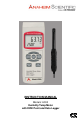
INSTRUCTION MANUAL Models: H300 Humidity/Temp Meter with DEW Point and Data Logger
Table of Content 1. Product Introduction ………………………………………… 3 1-1 Features ………………….………………………… 3 1-2 Applications ……………………………………...… 3 2. Safety Information …………………………………………… 4 2-1 Cautions ………………………………..………..… 4 2-2 Safety Symbols ………………………..…..……… 4 3. Specifications……………………………………...…………. 5 4. Operation Instructions……………………………………… 4-1 Unit Diagram ……………………………………… 4-2 Measuring Procedure ……………………….…... 4-3 Humidity & Temperature Measurement ..……… 4-4 DEW Point Measurement .…………….………… 4-5 Data Hold ……………………...
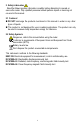
1. Product Introduction 1-1 Features Humidity, Temperature and Dew Point measure ments 0.
2. Safety Information Read the follow ing safety information carefully before attempting to operate or serv ice the meter. Only qualified personnel should perform repairs or serv ic ing not cov ered in this manual. 2-1 Cautions! DO NOT submerge the products mentioned in this manual in w ater or any other ty pes of liquids. This product is not designed for use in medical applications. The product can only be used to measure body temperature simply for reference.
5. Specifications Display Unit of Measurement 5 Digit LCD with bar graph indicator Humidity: %RH (Relative Humidity) Temperature: °C or °F Dew Point: °C or °F Temperature Compensation Automatic for humidity function Sampling Time of Data Logger Manual Pushing the data logger button once will save data one time Auto 1, 2, 10, 30, 60, 600, 1800, 3600 seconds Humidity / Temperature Range 0% to 95% RH Resolution 0.01% RH Humidity Accuracy >70%RH +(3% rdg.
4. Operation Instructions The H300 could take as long as ten minutes for the display to completely“ settle” and display the actual temperature or relative humidity level if the meter is exposed to two vastly different environments. The sensors used to make the environmental measurements must have time to acclimate to the test environment.
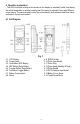
4-2 Measuring Procedure The H300 default unit of measure is °C. To switch to °F see section 5-1. The sampling time default for data logging is set at 2 seconds. To change this sampling time see section 4-7. 4-3 Humidity & Temperature Measurement 1. Plug the “ Probe Plug” (4-11, Fig. 1) into the “ Probe Input Socket” (4-10, Fig. 1). 2. Power on the meter by pressing the “ Power Button” (4-2, Fig.1) for 2 seconds. The LCD will show the units of measure on the displayafter a quick self test.
7. Press the “ REC Button” (4-4, Fig.1) momentarily to start the data log function. The REC symbol will be displayed on the LCD. The data logger function can save up to 1000 values of measure (either Humidity & Temp. or Dew Point & Te mp). 8. Press the “Logger Button” (4-6, Fig.1) and the meter will start logging. You will see the A flashing on the top of the LCD every time a logging event has occurred. The A flashing will match the number of seconds you set in the setup of the data logger function. 9.
5. Advanced Measuring Procedures Note: Cancel any Hold or Record functions before trying to perform and advanced measuring procedures. 1. Press and hold the “ SET Button” (4-6, Fig. 1) for about 3 seconds until the LCD displays “ Code” . Once you release the button you should see 1000 in the main display. 1000 Is the password code to allow advanced measuring procedures. To leave the setting menu press the “ ESC Button” (4-3, Fig.1). 2. Press the “ Enter Button” (4-4, Fig. 1). 4.
5-4 Clear Memory 1. Press and hold the “ Set Button” (4-6, Fig.1) for about 3 seconds. 2. The main LCD should then display1000. Now press the “ Enter Button” (4-4-, Fig. 1). 3. Press the “ Set Button” (4-6, Fig.1) three times and you will see the CLr marker in the bottom of the LCD. The top number is the number of stored data points. 4. Press the “ Function Button” (4-5, Fig. 1) and the top number will go to zero. 5. Press the “ Enter Button” (4-4-, Fig. 1) to clear memory. 6.
7. Send Data from RS232 Socket 1. Cancel Hold and REC functions. 2. Press and hold the “ Send Button” (4-5, Fig. 1) for about 2 seconds. You will see 232 in the bottom of the LCD. 3. Press the “ Send Button” (4-5, Fig. 1) and both the top and bottom display will begin to flash. At this ti me the data is being sent out the “ RS232 Socket” (4-9, Fig.1). 8. RS232 PC Serial Interface Information This instrument has RS232 PC serial interface via a 3.5 mm terminal (4-12, Fig. 1).
The 16 digit data stream will be displayed in the following format: D15 D14 D13 D12 D11 D10 D9 D8 D7 D6 D5 D4 D3 D2 D1D0 Each digit indicates the following status: D15 Start Word D14 4 D12 & D11 Indicator for Display °C = 01 °F = 02 % RH = 04 D10 Polarity: 0 = Positive / 1 = Negative D8 to D1 D0 Decimal Point (DP), position from right to left 0 = No DP, 1 = 1 DP, 2 = 2 DP, 3 = 3 DP Display reading, D1 = LSD, D8 = MSD Example: If the display reading is 1234, then D8 to D1 is: 00001234 End Word RS232 Setti
10. Service Inform ation Warranty Service: Please return the product in the original packaging with proof of purchase to the address below . Clearly state in writing the performance problem and return any leads, probes, connectors and accessories that you are using w ith the device. Non-Warranty Service: Return the product in the original packaging to the address below .
11. Lim ited Tw o-Year Warranty Anaheim Scientific w arrants to the original purchaser that its products and the component parts thereof, w ill be free from defects in workmanship and materials for a period of tw o years from date of purchase from an authorized Anaheim Scientific distributor. Anaheim Scientific w ill, w ithout charge, repair or replace, at its option, defective product or component parts. Returned product must be accompanied by proof of the purchase date in the form of a sales receipt.
Anaheim Scientific 22820 Savi Ranch Par kw ay Yorba Linda, CA 92887 U.S.A. www.anaheimscientific.com Printed in Taiw an / Ver. 1.