
Datasheet
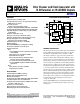


AD9523 Data Sheet
Rev. C | Page 2 of 60
TABLE OF CONTENTS
Features .............................................................................................. 1
Applications ....................................................................................... 1
Functional Block Diagram .............................................................. 1
General Description ......................................................................... 1
Revision History ............................................................................... 3
Specifications ..................................................................................... 4
Conditions ..................................................................................... 4
Supply Current .............................................................................. 4
Power Dissipation ......................................................................... 5
REFA,
REFA
, REFB,
REFB
, OSC_IN,
OSC_IN
, and ZD_IN,
ZD_IN
Input Characteristics ...................................................... 5
OSC_CTRL Output Characteristics .......................................... 6
REF_TEST Input Characteristics ............................................... 6
PLL1 Characteristics .................................................................... 6
PLL1 Output Characteristics ...................................................... 6
Distribution Output Characteristics (OUT0,
OUT0
to
OUT13,
OUT13
) .......................................................................... 7
Timing Alignment Characteristics ............................................ 8
Jitter and Noise Characteristics .................................................. 8
PLL2 Characteristics .................................................................... 8
Logic Input Pins—
PD
, EEPROM_SEL, REF_SEL,
RESET
,
SYNC
.............................................................................................. 9
Status Output Pins—STATUS1, STATUS0 ............................... 9
Serial Control Port—SPI Mode .................................................. 9
Serial Control Port—I²C Mode ................................................ 10
Absolute Maximum Ratings .......................................................... 12
Thermal Resistance .................................................................... 12
ESD Caution ................................................................................ 12
Pin Configuration and Function Descriptions ........................... 13
Typical Performance Characteristics ........................................... 16
Input/Output Termination Recommendations .......................... 18
Terminology .................................................................................... 19
Theory of Operation ...................................................................... 20
Detailed Block Diagram ............................................................ 20
Overview ..................................................................................... 20
Component Blocks—Input PLL (PLL1) .................................. 21
Component Blocks—Output PLL (PLL2) .............................. 22
Clock Distribution ..................................................................... 24
Zero Delay Operation ................................................................ 26
Reset Modes ................................................................................ 26
Power-Down Mode .................................................................... 27
Serial Control Port ......................................................................... 28
SPI/I²C Port Selection ................................................................ 28
I²C Serial Port Operation .......................................................... 28
SPI Serial Port Operation .......................................................... 31
SPI Instruction Word (16 Bits) ................................................. 32
SPI MSB/LSB First Transfers .................................................... 32
EEPROM Operations ..................................................................... 35
Writing to the EEPROM ........................................................... 35
Reading from the EEPROM ..................................................... 35
Programming the EEPROM Buffer Segment ......................... 36
Power Dissipation and Thermal Considerations ....................... 38
Clock Speed and Driver Mode ................................................. 38
Evaluation of Operating Conditions ........................................ 38
Thermally Enhanced Package Mounting Guidelines ............ 39
Control Registers ............................................................................ 40
Control Register Map ................................................................ 40
Control Register Map Bit Descriptions ................................... 45
Outline Dimensions ....................................................................... 57
Ordering Guide .......................................................................... 57