
Datasheet


AD9523 Data Sheet
Rev. C | Page 38 of 60
POWER DISSIPATION AND THERMAL CONSIDERATIONS
The AD9523 is a multifunctional, high speed device that targets
a wide variety of clock applications. The numerous innovative
features contained in the device each consume incremental
power. If all outputs are enabled in the maximum frequency and
mode that have the highest power, the safe thermal operating
conditions of the device may be exceeded. Careful analysis and
consideration of power dissipation and thermal management
are critical elements in the successful application of the AD9523
device.
The AD9523 device is specified to operate within the industrial
temperature range of –40°C to +85°C. This specification is
conditional, however, such that the absolute maximum junction
temperature is not exceeded (as specified in Table 17.). At
high operating temperatures, extreme care must be taken when
operating the device to avoid exceeding the junction temperature
and potentially damaging the device.
A maximum junction temperature is listed in Table 1 with the
ambient operating range. The ambient range and maximum
junction temperature specifications ensure the performance of
the device, as guaranteed in the Specifications section.
Many variables contribute to the operating junction temperature
within the device, including
• Selected driver mode of operation
• Output clock speed
• Supply voltage
• Ambient temperature
The combination of these variables determines the junction
temperature within the AD9523 device for a given set of
operating conditions.
The AD9523 is specified for an ambient temperature (T
A
). To
ensure that T
A
is not exceeded, an airflow source can be used.
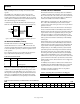
Use the following equation to determine the junction
temperature on the application PCB:
T
J
= T
CASE
+ (Ψ
JT
× PD)
where:
T
J
is the junction temperature (°C).
T
CASE
is the case temperature (°C) measured by the user at the
top center of the package.
Ψ
JT
is the value from Table 18.
PD is the power dissipation of the AD9523.
Values of θ
JA
are provided for package comparison and PCB
design considerations. θ
JA
can be used for a first-order
approximation of T
J
by the equation
T
J
= T
A
+ (θ
JA
× PD)
where T
A
is the ambient temperature (°C).
Values of θ
JC
are provided for package comparison and PCB
design considerations when an external heat sink is required.
Values of Ψ
JB
are provided for package comparison and PCB
design considerations.
CLOCK SPEED AND DRIVER MODE
Clock speed directly and linearly influences the total power
dissipation of the device and, therefore, the junction temperature.
Two operating frequencies are listed under the incremental power
dissipation parameter in Table 3. Using linear interpretation is
a sufficient approximation for frequency not listed in the table.
When calculating power dissipation for thermal consideration,
the amount of power dissipated in the 100 Ω resistor should be
removed. If using the data in Table 2, this power is already
removed. If using the current vs. frequency graphs provided in
the Typical Performance Characteristics section, the power into
the load must be subtracted, using the following equation:
Ω100
2
SwingVoltageOutputalDifferenti
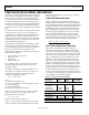
EVALUATION OF OPERATING CONDITIONS
The first step in evaluating the operating conditions is to
determine the maximum power consumption (PD) internal
to the AD9523. The maximum PD excludes power dissipated
in the load resistors of the drivers because such power is external
to the device. Use the power dissipation specifications listed in
Table 3 to calculate the total power dissipated for the desired
configuration. The base typical configuration parameter in
Table 3 lists a power of 428 mW, which includes one LVPECL
output at 122.88 MHz. If the frequency of operation is not listed
in Table 3, see the Typical Performance Characteristics section,
current vs. frequency and driver mode to calculate the power
dissipation; then add 20% for maximum current draw. Remove
the power dissipated in the load resistor to achieve the most
accurate power dissipation internal to the AD9523. See Table 30
for a summary of the incremental power dissipation from the base
power configuration for two different examples.
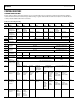
Table 30. Temperature Gradient Examples
Description Mode
Frequency
(MHz)
Maximum
Power (mW)
Example 1
Base Typical
Configuration
428
Output Driver 6 × LVPECL 122.88 330
Output Driver
6 × LVDS
245.76
110
Total Power
868
Example 2
Base Typical
Configuration
428
Output Driver 13 × LVPECL 983.04 2066
Total Power
2500