
Datasheet


AD9577 Data Sheet
Rev. 0 | Page 32 of 44
PLL1 PHASE FREQUENCY DETECTOR (PFD) AND
CHARGE PUMP
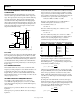
The PFD determines the phase difference error between the
reference divider output and the feedback divider output clock
edges. The outputs of this circuit are pulse-width modulated up
and down signal pulses. These pulses drive the charge pump
circuit. The amount of charge delivered from the charge pump to
the loop filter is determined by the instantaneous phase error. The
action of the closed loop is to drive the frequency and phase error
at the input of the PFD toward zero. Figure 42 shows a block
diagram of the PFD/CP circuitry.
D1 Q1
CLR1
REFCLK
HIGH
UP
D2 Q2
CLR2
HIGH
DOWN
CP
CHARGE
PUMP
3.3
V
GND
FEEDBACK
DIVIDER
09284-047
Figure 42. PFD Circuit Showing Simplified Charge Pump
PLL1 VCO
PLL1 incorporates a low phase noise LC-tank VCO. This VCO
has 32 frequency bands spanning from 2.15 GHz to 2.55 GHz.
At power-up, a VCO calibration cycle begins and the correct band
is selected based on the feedback divider setting (Na). Whenever a
new feedback divider setting is called for, the VCO calibration
process must run by writing 1 followed by 0 to the NewAcq bit,
Register X0[0].
PLL1 FEEDBACK DIVIDER
The feedback divider ratio, Na, is used to set the PLL1 VCO
frequency according to Equation 3. Note that the Na value is set
by adding the offset value of 80 to the value programmed to
Register AF0[5:0], where 80 is the minimum divider Na value.
The maximum Na value is 131. For example, to set Na to 85, the
AF0[5:0] register is set to 5.
SETTING THE OUTPUT FREQUENCY OF PLL1
For example, set the output frequency (f
OUT0
) on Port 0 to
156.25 MHz, the output frequency (f
OUT1
) on Port 1 to 100 MHz,
and both the reference frequency (f
REF
) and the PFD frequency
(f
PFD
) to 25 MHz.
The frequency f
OUT0
presented to OUT0 can be set according to
Equation 4.
The frequency f
OUT1
presented to OUT1 can be set according to
Equation 5.
To determine if both 156.25 MHz and 100 MHz can be derived
from a common f
VCO1
frequency in the 2.15 GHz to 2.55 GHz
range, use the lowest common multiple (LCM) of 156.25 MHz
and 100 MHz to determine the lowest VCO frequency that can
be divided down to provide both of these frequencies.
LCM(156.25 MHz, 100 MHz) = 2.5 GHz (6)
Therefore, set the VCO frequency to 2.5 GHz. With f
PFD
=
25 MHz, from Equation 3, Na must be set to 100.
For 156.25 MHz on Port 0, set
V0 × D0 = 16 (7)
This can be achieved by setting V0 to 4 and D0 to 4. For
100 MHz on Port 1, set
V1 × D1 = 25 (8)
This can be achieved by setting V1 to 5 and D1 to 5. With a
reference frequency of 25 MHz, the reference divider value, R,
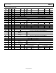
must be set to 1 by setting Register G0[1] to 0. Table 22
summarizes the register settings for this configuration.
Table 22. Register Settings for Example PLL1 Configuration
Parameter Divide Value I
2
C Register Register Value
Na 100 AF0[5:0] 010100
V0 4 ADV0[7:5] 100
D0 4 ADV0[4:0]
00100
V1 5 ADV1[7:5]
101
D1 5 ADV1[4:0]
00101
R 1 G0[1] 1
PLL2 INTEGER/FRACTIONAL-N PLL
The lower PLL in Figure 32, PLL2, is a fractional-N PLL. The
input frequency to the PLL from the reference circuit is f
PFD
.
The VCO frequency, f
VCO2
, is programmed by setting the values
for Nb, FRAC, and MOD according to
)(
2
M
OD
FRAC
Nbff
PFD
VCO
+×=
(9)
where Nb is programmable in the 80 to 131 range. To provide
the greatest flexibility and accuracy, both the FRAC and MOD
values can be programmed to a resolution of 12 bits, where
FRAC < MOD. The VCO output frequency can tune over the
2.15 GHz to 2.55 GHz range to fractional multiples of the PFD
input frequency.
By setting each of the VCO divider (V2 and V3) and output
divider (D2 and D3) values, the VCO frequency can be divided
down to the required output frequency, independently, for each
of the output ports, OUT2 and OUT3. The f
OUT2
frequency
presented to OUT2 can be set according to
D2V2
MOD
FRAC
Nb
ff
PFD
OUT2
×
+
×=
)(
(10)