
Datasheet


Data Sheet AD9577
Rev. 0 | Page 35 of 44
MARGINING
By asserting the MARGIN pin, a second full frequency map can
be applied to the output ports. The values for the Na, V0, D0,
V1, and D1 parameters, and the Nb, FRAC, MOD, V2, D2, V3,
D3 parameters must be programmed over the I
2
C, although default
values exist. There are some limitations: the output buffer signal
formats cannot be changed, and the PLL2 fractional-N settings,
such as power-down of the SDM, and bleed settings cannot be
changed. The margining feature can be used to set higher than
nominal frequencies on each of the ports to test system robustness.
When the MARGIN pin signal level is changed, a new frequency
acquisition is performed.
SPREAD SPECTRUM CLOCK GENERATION (SSCG)
By asserting the SSCG (spread spectrum clock generator) pin,
PLL2 operates in spread spectrum mode, and the output
frequency modulates with a triangular profile. As the clock
signal energy spreads out over a range of frequencies, it reduces
the peak power at any one frequency when observed with a
spectrum analyzer through a resolution bandwidth filter. This
result improves the radiated emissions from the part and from
the devices that receive its clock.
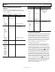
The triangular-wave modulation is implemented by controlling
the divide ratio of the feedback divider. This is achieved by
ramping the fractional word to the SDM. Figure 43 shows an
example implementation. The PFD frequency, f
PFD
, is 25 MHz.
The starting VCO frequency, f
VCO
, is 25 MHz × (99 + 3072/4096),
giving 2.49375 GHz. By continuously ramping the FRAC word
down and up, this frequency is periodically reduced to 25 MHz ×
(99 + 1029/4096) = 2.481281 GHz. This results in a triangular
frequency modulation profile, with a peak downspread (that is,
peak percentage frequency reduction) of −0.5%. By controlling
the step size, number of steps, and the step rate, the modulation
frequency is adjusted.
f
PFD
f
PFD
VCO
2.15GHz
TO
2.55GHz
PFD/CP
THIRD
ORDER LPF
DIVIDE BY
80 TO 131
FEEDBACK
DIVIDER
N
B
SDM
3-BIT
0
1
FRAC
FRAC_TRIWAVE
SSCG
MOD
CKDIV
FRAC
FRACSTEP
NUMSTEPS
SSCG
TRIWAVE
GENERATOR
FRAC_TRIWAVE
f
VCO
f
VCO
– 0.5%
TIME
VCO
FREQUENCY
TIME
FRAC_TRIWAVE = 3072
FRAC_TRIWAVE = 1029
09284-048
Figure 43. Spread Spectrum Clock Generator with Triangular Wave
Modulation, f
PFD
= 25 MHz
Basic Spread Spectrum Programming
The SSCG is highly programmable; however, most applications
require that the frequency modulation rate be between 30 kHz
and 33 kHz and that the peak frequency deviation be −0.5%
downspread. The AD9577 supports downspread only, with a
maximum deviation of −0.5%.
The key parameters (which are not themselves registers) that
define the frequency modulation profile include the following:
• f
MOD
, which is the frequency of the modulation waveform.
• FracRange, which determines the peak frequency deviation
by setting the maximum change in the FRAC value from
the nominal.
The following equations determine the value of these parameters:
FracRange = FracStep × NumSteps (12)
CkDivNumSteps
f
f
PFD
MOD
××
=
2
(13)
where the following are programmable registers:
• NumSteps is the number of fractional word steps in half the
triwave period.
• FracStep is the value of the fractional word increment/
decrement, while traversing the tri-wave.
• CkDiv is the integer value by which the reference clock
frequency is divided to determine the update rate of the
triangular-wave generator, that is, the step update rate.
• f
PFD
is the PFD frequency.