MODEL: 30& &36 36 MODEL: PRESTO TRINA 30 IMPORTANT SAFETY INSTRUCTIONS Carefully read the following important information regarding installation safety and maintenance. Keep these instructions for future reference.
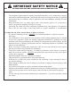
IMPORTANT SAFETY NOTICE READ ALL INSTRUCTIONS BEFORE INSTALLING AND OPERATING THIS APPLIANCE ● ● ● ● The installation in this manual is intended for qualified installers, service technicians or persons with similar qualified background. Installation and electrical wiring must be done by qualified professionals and in accordance with all applicable codes and standards, including fire-rated construction.
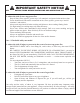
IMPORTANT SAFETY NOTICE READ ALL INSTRUCTIONS BEFORE INSTALLING AND OPERATING THIS APPLIANCE To reduce the risk of stove top grease fire: ● ● ● ● ● ● ● Keep all fans, filters, spacers, grease trays*, oil container* and grease-laden surfaces clean. Grease should not be allowed to accumulate on fan, filters, spacers, grease trays* and oil container*, and surfaces. Always turn range hood ON when cooking at high heat or when cooking flaming foods. Use high settings on cooking range only when necessary.
PARTS SUPPLIED: 4
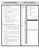
VENTING REQUIREMENTS: • • • • • • • Vent system must terminate to the outside (Roof or side wall). DO NOT terminate the vent system in an attic or other enclosed area. DO NOT use 4” (10.2 cm) laundry-type wall caps. Use metal/aluminum vent only. Rigid metal/ aluminum vent is recommended. DO NOT use plastic vent. Always keep the duct clean to ensure proper airflow. Calculate the following figures before installation: 1. Distance from the floor to the ceiling 2.
IMPORTANT: • • • • • • • • A minimum of 6” round or 3-1/4 x 10” rectangular duct (purchased separately) must be used to maintain maximum airflow efficiency. Always use rigid type metal/aluminum ducts if available to maximize airflow when connecting to provided duct. Please use Duct Run Calculation below to compute total available duct run when using elbows, transitions and caps. ALWAYS, when possible, reduce the number or transitions and turns.
VENTING METHODS: • • This range hood is factory set for venting through the roof or wall. Vent work can terminate either through the roof or wall. To vent through a wall, a 90° elbow is needed. IMPORTANT: • • • • NEVER exhaust air or terminate duct work into spaces between walls, crawl spaces, ceiling, attics or garages. All exhaust must be ducted to the outside. Use metal/aluminum duct work only. Fasten all connections with sheet metal screws and tape all joints with certified Silver Tape or Duct Tape.
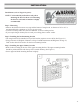
ELECTRICAL REQUIREMENTS: IMPORTANT: Observe all governing codes and ordinances. It is the customer’s responsibility to contact a qualified electrical installer. If codes permit and a separate ground wire is used, it is recommended that a qualified electrician determine that the ground path is adequate. A 120-Volt, 60 Hz, AC-only, fused electrical supply is required on a separate 15-amp circuit, fused on both sides of the line. DO NOT ground to a gas pipe.
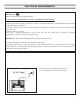
PREPARATIONS: Advanced Preparations: • Be familiar with the controls of the range hood by reading through Range Hood Operations, Page 15. • Place the range hood on a flat, stable surface. Connect the range hood to a designated standard outlet (120-Volt, 60Hz, AC only) and turn on the range hood. Verify all operations of the range hood by referring to Range Hood Operations.
INSTALLATION: Installations (refer to Page 4 for parts): NOTE: Use threaded drywall anchors only when mounting the hood on sheet rock. Mounting the hood on wall studs or lumbars is highly recommended. Step 1: Measuring • Measure the distance between stove top and the bottom of range hood. A distance of 24” to 30” is recommended with a minimum of 30” for gas stove tops.
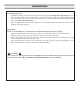
INSTALLATION CONTINUE: Step 4: Venting • Fix the damper on the top vent of hood with 4 screws (requires screw C). If ventilation system is equipped with an external air duct with a different diameter, apply a reduction fitting. However, for maximum performance and safety, a 6” round ducting is recommended. (See Figure # 2) 3 2 A Step 5: Mounting the hood on the wall • Hang the range hood on the hooks of the lower mounting bracket. (See Figure # 3) • Screw the range hood to the wall (requires screw A).
INSTALLATION CONTINUE: Step 6: Installing filters • To install filters for the following four steps (See Figure # 6): - Angle the filter into slots at the back of the hood. - Push the button on handle of the filter. - Release the handle once the filter fits into a resting position. - Repeat to install all filters. 6 Step 7: Test hood • Turn power On in control panel. • Check all lights and fan operations. • Make sure to leave this Installation Manual for the homeowner.
CONTROL PANEL OPERATION: Increase Speed Decrease Speed Timer Light Control Panel Layout and Buttons Configurations: Electronic Controls with Time Delay • Lights: • Press the light button • Power settings: to turn halogen lights on and off. • Press the button + once and the motor starts to operate at Low speed. • Press the button + again and the motor will reach Medium speed. • Press the button + once more and the motor will reach High speed.
REPLACING THE BULBS: Replacing the light bulbs: • This range hood uses halogen bulbs: 20W 12V type G4. • Make sure the range hood is unplugged or turn OFF breaker. • Place a flat-head screwdriver between light cover and housing to remove cover. • Gently pull defective bulb straight out and discard. • Wear a cotton glove or use a cloth to handle the replacement bulb. (DO NOT handle with bare fingers as this may shorten the life of the bulb). Push gently but securely into light socket.
MOUNTING BRACKETS: Upper Chimney Bracket 4 7/8” (124 mm) 8 5/8” (219 mm) Lower Chimney Bracket 8” (203 mm) 4 5/8” (119 mm) 8 5/8” (219 mm) Mounting Bracket Hook 7 7/8” (200 mm) 3 15/16” (100 mm) 3 15/16” (100 mm) 8 5/8” (219 mm) 15
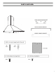
MEASUREMENTS AND DIAGRAMS: 6 3/4’’ (170mm) 8 3/4’’ (222mm) 17” - 33.
TROUBLE SHOOTING: 1) If the range hood or halogen light does not operate after installation: • Check if the range hood has been plugged in, make sure that all power has been turned back ON,fused not blown and all electrical wiring are properly connected. 2) The range hood vibrates when the blower is on: • The range hood might not have been secured properly on to the ceiling or wall. 3) The blower or fan seems weak: • Check that the duct sized used is at least 6” or 3-1/4 x 10”.
RANGE HOOD ASSEMBLY: No.
SPECIFICATIONS: Body design Stainless steel Power rating 120V / 60Hz (USA & Canada standard) General input power 250W (210W + 2x20W) Motor input power 210W Ampere 2.
BLOWER ASSEMBLY: No. 1 Grid 2 Blower 3 Impeller Description No. 4 Motor Description ELECTRICAL ASSEMBLY: No. 1 2 3 4 5 Description Electrical box base PCB Electrical cover Capacitor Screw (ST3*10) No.
USE AND CARE INFORMATION: Operations: • Read and understand all instructions and warnings in this manual before operating the appliance. Save these instructions for future reference. • Always leave safety grills and filters in place. Without these components, operating fans could catch on to hair, fingers and loose clothing. • NEVER dispose cigarette ashes, ignitable substances, or any foreign objects into fans. • NEVER leave cooking unattended.
LIMITED PRODUCT WARRANTY Subject to the limitations, exclusions and disclaimers hereof, AMS warrants exclusively to the original purchaser (the “Purchaser”) of this Ancona Range hood product (the “Product”) that it shall be free from defects in material or workmanship (the “Limited Product Warranty”). The duration of the Limited Product Warranty is 12 months from the date of original purchase (the “Warranty Period”).