MODEL: SD330 & SDW330 IMPORTANT SAFETY INSTRUCTIONS Carefully read the following important information regarding installation safety and maintenance. Keep these instructions for future reference.
IMPORTANT SAFETY NOTICE READ AND SAVE THESE INSTRUCTIONS READ ALL INSTRUCTIONS BEFORE INSTALLING AND OPERATING THIS APPLIANCE ● The installation in this manual is intended for qualified installers, service technicians or persons with similar qualified background. Installation and electrical wiring must be done by qualified professionals and in accordance with all applicable codes and standards, including fire-rated construction.
IMPORTANT SAFETY NOTICE READ AND SAVE THESE INSTRUCTIONS READ ALL INSTRUCTIONS BEFORE INSTALLING AND OPERATING THIS APPLIANCE WARNING: TO REDUCE RISK OF A RANGE TOP GREASE FIRE: a) Never leave surface units unattended at high settings. Boilovers cause smoking and greasy spillovers that may ignite. Heat oils slowly on low or medium settings. b) Always trun hood ON when cooking at high heat or when flambeing food (i.e. Crepes Suzette, Cherries Jubilee, Peppercorn Beef Flambé).
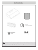
PARTS SUPPLIED: Filters (2 pcs) Suction Cup (to remove GU10 lightbulb) Vent / Damper Damper Screws (10 pcs) Rubber Bushing Hardware Note: For safety reasons, range hood mounting screws and anchors will not be included due to the variation of cabinetry constructions and wall material. Please consult your installation specialist regarding the optimal type of mounting screws and wall anchors to suit your home’s construction.
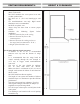
VENTING REQUIREMENTS: • • • • • • • HEIGHT & CLEARANCE: Vent system must terminate to the outside (Roof or side wall). DO NOT terminate the vent system in an attic or other enclosed area. DO NOT use 4” (10.2 cm) laundry-type wall caps. Use metal/aluminum vent only. Rigid metal/ aluminum vent is recommended. DO NOT use plastic vent. Always keep the duct clean to ensure proper airflow. Calculate the following figures before installation: 1. Distance from the floor to the ceiling 2.
IMPORTANT: • • • • • • • • A minimum of 6” round or 3-1/4 x 10” rectangular duct (purchased separately) must be used to maintain maximum airflow efficiency. Always use rigid type metal/aluminum ducts if available to maximize airflow when connecting to provided duct. Please use Duct Run Calculation below to compute total available duct run when using elbows, transitions and caps. ALWAYS, when possible, reduce the number or transitions and turns.
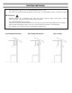
VENTING METHODS: • • This range hood is factory set for venting through the roof or wall. Vent work can terminate either through the roof or wall. To vent through a wall, a 90° elbow is needed. IMPORTANT: • • • • NEVER exhaust air or terminate duct work into spaces between walls, crawl spaces, ceiling, attics or garages. All exhaust must be ducted to the outside. Use metal/aluminum duct work only. Fasten all connections with sheet metal screws and tape all joints with certified aluminum or foil tape.
ELECTRICAL REQUIREMENTS: IMPORTANT: Observe all governing codes and ordinances. It is the customer’s responsibility to contact a qualified electrical installer. If codes permit and a separate ground wire is used, it is recommended that a qualified electrician determine that the ground path is adequate. A 120-Volt, 60 Hz, AC-only, fused electrical supply is required on a separate 15-amp circuit, fused on both sides of the line. DO NOT ground to a gas pipe.
PREPARATIONS: Advanced Preparations: • Be familiar with the controls of the range hood by reading through Range Hood Operations, Page 14. • Place the range hood on a flat, stable surface. Connect the range hood to a designated standard outlet (120-Volt, 60Hz, AC only) and turn on the range hood. Verify all operations of the range hood by referring to Range Hood Operations.
NEW INSTALLATION: Installations (refer to page 4 for parts): NOTE: Use threaded drywall anchors only when mounting the hood on sheet rock. Mounting the hood on wall studs or lumbars is highly recommended. Hardware Note: For safety reasons, range hood mounting screws and anchors will not be included due to the variation of cabinetry constructions and wall material. Please consult your installation specialist regarding the optimal type of mounting screws and wall anchors to suit your home’s construction.
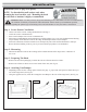
NEW INSTALLATION: Step 5: Installing the Hood Fig #4 • Using measurements provided on Page 16, measure and drill 4 holes into bottom of cabinet. (See Fig #4) • Depending on exterior venting chosen (See page 7), use measurements provided on Page 16 and cut vent hold in cabinet. • Align range hood to the holes in the bottom of the cabinet and screw in using the supplied screws. (See Fig #4) Step 6: Venting certified aluminum or foil tape so that it is air tight.
REPLACEMENT INSTALLATION: ep 5: Venting Installations (refer to Page 4 for parts): NOTE: Use threaded drywall anchors only when mounting the hood on sheet rock. Mounting the hood on wall studs or lumbars is highly recommended. Step 1: Measuring • Measure the distance between the cooking surface and the bottom of the range hood. A distance of 24” to 30”. Step 2: Preparing The Hood • Remove the unit from packaging. Position the unit on a flat non-abrasive surface.
REPLACEMENT INSTALLATION: Step 5: Venting certified aluminum or foil tape so that it is air tight. Please check the building codes in your city to learn which tape product is recommended. Fig #5 Step 6: Electrical Connection 5) DON’T FORGET TO CONNECT THE GROUND! • Open the wiring compartment and secure the leads inside. • Please use the bushing provided on the cut-out opening to protect the electrical wires. • WARNING: ALL CONNECTORS MUST BE ENCLOSED IN THE WIRING COMPARTMENT.
• Lights: o Press the light button • Power settings: o Press the o Press the o Press the o Press the to turn halogen lights on and off. button once and the motor starts to operate at Low speed. button again and the motor will reach Medium speed. button once more and the motor will reach High speed . button to turn the fan off.
Replacing the light bulbs: This range hood uses halogen bulbs: 35W 120V Type GU-10 1. Make sure the electrical power to the range hood is turned off. Please note that the light bulbs may be hot. Allow enough time to let the light bulbs cool off before attempting to change them. Fig #7 2. Attach the black rubber suction piece, included with your range hood, to the outside glass part of the bulb. Press the bulb inwards. DO NOT push too hard as bulb “legs” may break off. (See Fig #7) 3.
MEASUREMENTS AND DIAGRAMS: 11 c m (4 3 /8 i n./p o.) o.) cm 8.3 .) po 16 c m m .4 c ./ 0 in cm (3 1 /4 in (1 ./po .) 25 (6 5 /16 in./ po. ) m 6c 65. 7/ (25 m 6c 30.5 cm (12 12 . 7 c m ( 5 i n . /p o . ) 34. 48 c m (19 25.4 in./ ( 13 5/ .) po ./ 8 in po. in./ ) 75 po. ) 8.3 cm cm .) po ./ 8 in 4.5 cm 2.5 ( 1 3 /4 i n . /p o . ) ./p in (1 ( 10 (3 1/4 in./po .) in./p o.) 16 cm (29 1/ .) po .
TROUBLE SHOOTING: 1) If the range hood or halogen light does not operate after installation: • Check if the range hood has been plugged in, make sure that all power has been turned back ON,fused not blown and all electrical wiring are properly connected. 2) The range hood vibrates when the blower is on: • The range hood might not have been secured properly on to the ceiling or wall. 3) The blower or fan seems weak: • Check that the duct sized used is at least 6” or 3-1/4 x 10”.
RANGE HOOD ASSEMBLY: 10 9 8 7 6 5 4 3 2 1 Light Panel Electronic Box Cover Capacitor PCB Switch Switch Cover Switch Bracket Electronic Box Base Electronic Box Bracket Housing 1 1 1 1 1 1 1 1 1 1 19 18 17 16 15 14 13 12 11 18 Wires Strengthen Strip Filters Light Bulbs Lamp Holders Safety Screen Propeller Cage Propeller Motor 1 1 2 2 2 1 1 1 1
SPECIFICATIONS: Body design Stainless steel Power rating 120V / 60Hz (USA & Canada standard) cETLus Certified Total input power 170W Motor input power 100W Total Ampere 1.45A Levels of speed control 3 levels Interference Protection Radio frequency interference protected Noise Level Low Speed 2.
BLOWER ASSEMBLY: No. 1 Propeller Cage 2 Motor 3 Propeller Description No. 4 Safety screen Description ELECTRICAL ASSEMBLY: No. 1 2 3 4 5 Description Electrical box cover PCB Capacitor Electrical box base Electrical box bracket No.
USE AND CARE INFORMATION: Operations: • Read and understand all instructions and warnings in this manual before operating the appliance. Save these instructions for future reference. • Always leave safety grills and filters in place. Without these components, operating fans could catch on to hair, fingers and loose clothing. • NEVER dispose cigarette ashes, ignitable substances, or any foreign objects into fans. • NEVER leave cooking unattended.