This manual must be kept with the appliance February 2012 Part No E191 Addendum CSC Temperature Selection Procedure Auto-Ignition Addendum Natural Gas, Propane & Butane Fired Storage Water Heaters MODELS CSC39, CSC59, CSC78, CSC93, CSCL39, CSCL59, CSCL78, CSCL93 Auto Ignition Working towards a cleaner future
TEMPERATURE ADJUSTMENT (24V CONTROL SYSTEM) The water heater temperature setting is adjusted by using the control display mounted to the front of the control panel of the water heater. The water heater thermostat is set at the lowest setpoint of 70°F when shipped from the factory. The control display shows the temperature setpoint in degrees Fahrenheit (°F) or degrees Celsius (°C), and the status of the water heater (“Idle” or “Heating”).
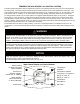
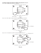
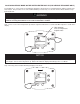
To Increase Setpoint Temperature Step 1: Depress and hold “Temperature Up” button until desired setpoint temperature appears in the display. °F idle Status Operational SELECT SET % Step 1 Step 2: “Setpoint” indicator begins flashing in the display after pressing “Temperature Up” button. "Setpoint" flashes °F setpoint idle Status Operational SELECT SET % Step 2 Step 3: Press “SET” button for new setting to take effect immediately. “Setpoint” will stop flashing.
To Decrease Setpoint Temperature Step 1: Depress and hold “Temperature Down” button until desired setpoint temperature appears in the display. °F idle Status Operational SELECT SET % Step 1 Step 2: “Setpoint” indicator begins flashing in the display after pressing “Temperature Down” button. "Setpoint" flashes °F setpoint idle Status Operational SELECT SET % Step 2 Step 3: Press “SET” button for new setting to take effect immediately. The setpoint will stop flashing.
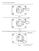
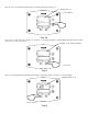
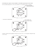
To Change Temperature Format in Display from °F to °C or ˚C to ˚F: Step 1: Press “SELECT” button until °F/°C is displayed. °F °F/°C idle Status Operational & SELECT Press select SET Step 1 Step 2: Press “SET” button to change temperature format. Symbol °F/°C will flash. °F °F/°C idle Status Operational SELECT % % SET °F/°C Flashes Step 2 Step 3a: Press “Temperature Up” button to change temperature format to °C.
Step 3b: Press “Temperature Down” button to change temperature format to °F. Changes to "°F" °F/°C Flashes °F °F/°C idle Status Operational SELECT SET % Step 3b Step 4: Press “SET” button to confirm ˚F or ˚C format. °F/°C will stop flashing. Setpoint display will appear in the format selected (˚F or ˚C) in 10 seconds.
An automatic gas shut-off device (ECO) is incorporated in the sensor and control board which will shut off all gas supply to the burner and pilot if the water heater temperature exceeds 200°F (93°C). Should the ECO function (open), the water temperature should be reduced to approximately 120°F (49°C) and follow applicable Lighting Instructions to place the water heater in operation.
SECTION X: MAINTENANCE The following maintenance should be performed by a qualified service technician at the minimum periodic intervals suggested below. In some installations, the maintenance interval may be more frequent depending on the amount of use and the operating conditions of the water heater. Regular inspection and maintenance of the water heater will help to insure safe and reliable operation. 1.
ACCESSING SERVICE MODE ON THE WATER HEATER DISPLAY (FOR SERVICE PERSONNEL ONLY) The display has a “service mode” for changing the maximum setpoint and accessing information in aiding servicing of the water heater. This procedure is for service and installation personnel only. To enter the Service Mode, follow the steps illustrated below: WARNING The following procedure is for service and installation personnel only.
The following is the sequence of modes available in “Service Mode” by pressing the “Select” button: Error Code Number (Display/Reset). This is only shown if there is an operating error in the “User Mode”. Error Code Shown in Water Heater Display Status Service Needed SELECT Lockout RESET 1. Max Setpoint (Display/Change) Max Setpoint value Water Heater Display °F Max Setpoint idle Status Operational & SELECT SET 2a.
2b. Water Temperature - Upper Sensor (Displays if there is an upper sensor – some models) °F idle Status Operational Upper Sensor & SELECT SET 2c. Water Temperature - Lower Sensor (Displays if there are two sensors) °F idle Status Operational & Lower Sensor SELECT SET 3.
4. Setpoint (Display/Change) °F setpoint idle Status Operational & SELECT SET 5. ˚F/˚C (Display/Change) °F °F/C° idle Status Operational & SELECT SET 6.
7. Software Version (Display only) Soft idle Status Operational & SELECT SET 8. Error Code History (Displays if there are present error codes or up to 10 previous error codes). Water Heater Display will show -- if there are no error codes. No current error codes idle Status Operational & SELECT SET To change the Maximum Setpoint Limit (Max Setpoint) for the temperature setpoint: WARNING Setting the water temperature to the maximum set point can result in scalding hot water delivered to the taps.
Step 2: Press “Set” button to enter setting mode. “Max Setpoint” will flash to indicate setting mode. "Max Setpoint" Flashes °F Max Setpoint idle Status Operational % SELECT SET Step 3: Press the “UP” or “DOWN” buttons to change the maximum setpoint value. This will limit the maximum setpoint the user can select. Note: The maximum setpoint is approximately 180˚F.
Step 5: 30 Seconds after the last button press, the Water Heater Display will go back to “User Mode”. It will read “Max Setpoint” without showing a temperature value if the temperature setpoint is at the maximum setting. The Water Heater Display can be set back to the “User Mode” immediately by pressing both the “Temperature Up” and “Select” buttons together for 3 seconds.
Step 2: For water heaters using two temperature sensors, pressing the “Select” button again displays the Upper Sensor temperature reading. “Upper Sensor” will be displayed in the lower right side of the status window of the water heater display. °F idle Status Operational Upper Sensor & SELECT SET Step 3: For water heaters using two temperature sensors, pressing the “Select” button again displays the Lower Sensor temperature reading.
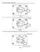
To Display and Change Temperature Setpoint: Step 1: In “Service Mode” press the “Select” button until “Setpoint” is shown in the water heater display. °F setpoint idle Status Operational & SELECT SET Step 2: Press the “Set” button to enter the setting mode. “Setpoint” will flash in the water heater display.
Step 4: To lower the temperature setpoint, press the “Temperature Down” button until the desired temperature is shown on the water heater display. "Setpoint" Flashes °F setpoint idle Status Operational SELECT SET % Step 5: When the desired setpoint is reached on the water heater display, press the “Set” button to confirm the new setpoint. “Setpoint” stops flashing in the water heater display.
Step 2: Press “Set” button to change temperature format. “˚F/˚C” symbol will flash in the water heater display. "°F/°C" Flashes °F °F/C° idle Status Operational % SELECT SET Step 3a: Press “Temperature Up” button to change temperature format to ˚C. Changes to "°C" "°F/°C" Flashes °C °F/C° idle Status Operational SELECT SET % Step 3b: Press “Temperature Down” button to change temperature format to ˚F.
Step 4: Press “Set” button to confirm ˚F or ˚C format. ˚F/˚C will stop flashing. "°F/°C" Symbol Stops Flashing °F °F/C° idle Status Operational % SELECT SET Step 5: Pressing “Select” button will return display to setpoint in format selected (˚F or ˚C) immediately.
How to reset the control from Lockout Conditions: WARNING The following procedure is for service and installation personnel only. Resetting lockout conditions without correcting the malfunction can result in a hazardous condition. If an error code is displayed (except for #4, low flame sense current), the water heater will be in a “lockout condition” with the water heater display showing the error code number and “Service Needed” in the status section of the display window.
Error Codes and Error History Display: If there is an operating problem with the water heater, an error code number will appear on the water heater display with “Service Needed” to the right of the “Status” indicator. The error code label is located below the water heater display and the following section in this Installation and Operating Instruction Manual explains the error codes with corrective actions to repair the water heater.
Step 2: Press the “Temperature Down” button to select the error code index, starting with the most recent error code “10”. Error Code Index idle Status Operational SELECT SET % Step 3: Press the “Select” button to view the error code for “code 10”. If there is a number displayed, note what the number is. The label next to the water heater display will identify the code number.
Step 4: Press the “Temperature Down” button to change to the previous code index, code #9. Error Code Index idle Status Operational SELECT SET % Step 5: Press the “Select” button for code index #9 to view if there are any code numbers.
Step 6: Continue pressing the “Temperature Down” button to change to the next error code index and press “Select” to view the error code number, if any, for that index number. Continue on to index #1, the oldest error code index. The water heater display will store up to 10 error codes with the oldest code starting in code index #1 with the most recent code in code index #10. Step 7: 10 seconds after the last button press, the Water Heater Display will revert back to the current error code display.
Error Code Definition of Code Cause of Problem and Actions Taken to Correct 6 Flame Sensed Out of Normal Sequence (Before Opening Gas Valve or After Closing Gas Valve) Check to make sure gas valve has closed. No voltage should be present at the gas valve before or after ignition cycle. Make sure wire positions on the wire harness are correct. If gas valve is stuck open, replace.
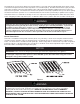
Procedure for Checking Thermostat Sensors Set the thermostat above water temperature (See temperature adjustment section) and observe system through one (1) complete cycle. Make sure system operates as desired. To check the upper sensor or lower sensor assembly, compare the resistance of the sensor terminals (blue leads for upper sensor, yellow and black lead for lower sensor) as measured by an ohmmeter to the water temperature as measured by an accurate thermometer.
Publication Date: 0212 0087 Baxi Commercial Division Wood Lane, Erdington, Birmingham B24 9QP Sales: Technical: 0845 070 1056 0845 070 1057 Email: andrews@baxicommercialdivision.com www.andrewswaterheaters.co.