Installation Guide, Operation and Maintenance Manual ECoflo HIGH EFFICIENCY CONDENSING STORAGE WATER HEATER FOR NATURAL GAS AND PROPANE (LPG) EC230/600, EC230/960, EC380/980, EC380/1400 EC230/700 EC380/740 EC380/1220 LEC230/600, LEC230/960, LEC380/980, LEC380/1400 LEC230/700 LEC380/740 LEC380/1220 THIS MANUAL MUST BE KEPT WITH THE APPLIANCE March 2007 Part No.
the nation’s favourite for PLUMBING & HEATING SUPPLIES FREE SHIPPING SECURE PAYMENTS on all orders over £100 to mainland UK shop online with confidence FINANCE AVAILABLE PRICE MATCH spread the cost with low interest rates always get the best deals available we have H U G E R E D U C T I O N S ON THOUSANDS OF ITEMS Boilers Bathroom suites Radiators Kitchen sinks & taps Heating controls Showers Pipes & ittings Wet rooms Cylinders Towel warmers Fires Bathroom furniture Renewable energy
Copyright Andrews Water Heaters 2006 Reproduction of any information in this publication by any method is not permitted unless prior written approval has been obtained from Andrews Water Heaters. Andrews Storage Water Heaters have been designed and manufactured to comply with current International standards of safety. In the interests of the health and safety of personnel and the continued safe, reliable operation of the equipment, safe working practices must be employed at all times. The attention of U.K.
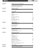
CONTENTS SECTION 1 SECTION 2 SECTION 3 SECTION 4 PAGE GENERAL AND SAFETY INFORMATION General Information British Standards and Codes of Practice Health and Safety Regulations 1993 Effectiveness in Combating Legionellae 2 2 3 3 TECHNICAL DETAILS Technical Data Dimensions and Clearances 4 5 INSTALLATION Introduction Location Features Component Specification Unpacking Location Gas Supply - Natural Gas Gas Supply - Propane Gas Electrical Supply Flue System Air Supply and Ventilation Water Quality and
SECTION 1 GENERAL AND SAFETY INFORMATION GENERAL The Andrews Water Heater has been designed for use with NATURAL GAS OR LPG and is INFORMATION manufactured to give an efficient, reliable and long service life. To ensure the continued, trouble-free operation of your heater at maximum efficiency, it is essential that correct installation, commissioning, operation and service procedures are carried out strictly in accordance with the instructions given in this manual.
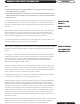
GENERAL AND SAFETY INFORMATION SECTION 1 Terms: a. Andrews Water Heaters accepts no liability for any damage resulting from failing to accurately follow the instructions. b. When replacing parts during maintenance, only original parts from Andrews Water Heaters should be used; these can be recognised by the name of the manufacturer printed on them.
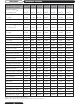
SECTION 2 TECHNICAL DETAILS Model Reference - Natural Gas EC230/600 EC230/700 EC230/960 EC380/740 EC380/980 EC380/1220 EC380/1400 Model Reference - Propane LEC230/600 LEC230/700 LEC230/960 LEC380/740 LEC380/980 LEC380/1220 LEC380/1400 Natural gas, category I2H Gas consumption G20 3.41m3/h 4.09m3/h 5.43m3/h 4.09m3/h 5.43m3/h 6.82m3/h 7.92m3/h Heat input gross 36.6 kW 43.9 kW 58.3 kW 43.9 kW 58.3 kW 73.2 kW 85.0 kW Heat output 35.1 kW 41.3 kW 54.2 kW 43.0 kW 57.1 kW 71.
TECHNICAL DETAILS SECTION 2 ECOflo Models EC230/600, EC230/700, EC230/960 FLUE EXHAUST OUTLET 100MM CLEARANCE 500MM SERVICE CLEARANCE FOR FLUE SYSTEM 210 GAS CONNECTION AIR INTAKE 100MM CLEARANCE ON/OFF SWITCH THERMOSTAT KNOB T&P VALVE ON/OFF SWITCH COMBUSTION AIR INLET THERMOSTAT KNOB 3/4" BSP GAS CONNECTION GAS CONNECTION COMBUSTION AIR INLET T&P VALVE CONNECTION HOT WATER OUTLET T&P VALVE CONNECTION 1448 1 1/2" BSP HOT WATER OUTLET 1 1/2" BSP COLD WATER INLET DRAIN/RETURN CONNECTION CLEA
SECTION 3 INSTALLATION INTRODUCTION THE LAW REQUIRES THAT INSTALLATION IS CARRIED OUT BY A PROPERLY QUALIFIED PERSON Installations must be carried out in accordance with Gas safety (Installation and Use) Regulations 1998, Building Regulations, The Water Supply (Water Fittings) Regulations 1999 and any requirements of the local Gas Authority, Local Authority, Water and Fire Authorities and the current British Standards and Codes of Practice listed in Section 1.
INSTALLATION SECTION 3 ECOflo is the latest addition to the Andrews range of condensing storage water heaters and is designed for large domestic, commercial and industrial applications. The high efficiency units incorporate Vitraglas® silica glass lined tanks to provide protection against the corrosive effect of hot water and guarantees a longer working life.
SECTION 3 INSTALLATION This water heater contains the following features: MAIN POWER The front panel of this water heater has a lighted ON/OFF switch, which is illuminated when ON/OFF SWITCH the main power is turned on to indicate power to the water heater. COMBUSTION The water heater is equipped with a self-compensating negative pressure pre-mix SYSTEM combustion system. As the blower operates, air is drawn in through the air intake and into a venturi, which pulls gas from the gas valve.
INSTALLATION SECTION 3 This water heater is a condensing type unit and requires a drain to be located in close proximity to allow the condensate to drain safely. The condensate drains from the unit at the base of the exhaust tee piece located near the bottom of the unit. The exhaust tee is provided with a 32mm dia connection. A condense siphon is supplied in the flue kit which should be connected to the 32mm connection at the base of the exhaust tee.
SECTION 3 INSTALLATION Thermal Efficiency up to 98.0% - Fully condensing design. Three Pass Flue System - The three pass flue system keeps the hot combustion gases moving at a high velocity. The combination of high turbulence and velocity causes an enormous rate of heat transfer into the water. Low NOx Premix Power Burner - Developed for the ECOflo Range, a turbulent flame shoots down the submerged combustion chamber.
INSTALLATION Fenwal 35-655305-121 Hot Surface Ignition Control, CE listed. 3 Trials for Ignition, 15 second pre-purge timing, 15 second igniter heat up time, 4 second trial for ignition. 24 volt input to control. SECTION 3 IGNITION SYSTEM COMPONENTS Omron G2R-1A-T-AC24 relays (VDE listed) used for high voltage switching of hot surface igniter and combustion blower from the 24 volt outputs of the Fenwal control. Saint Gobain 230 volt hot surface mini igniter.
SECTION 3 INSTALLATION VENTING SYSTEM A condensate tee with a silicone seal is connected to the plastic exhaust pipe and interfaces with the flue system. The tee connection has a 32mm condensate drainpipe connection to allow the siphon to be fitted. The waste pipe will then be taken from the siphon outlet to drain. A section of aluminum flue pipe will run to the top of the water heater to connect to the air intake tee.
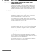
INSTALLATION 1. 2. SECTION 3 Remove all banding and pry off crate sides carefully so as not to damage the water heater. Carefully roll/lift the water heater from the crate base. REMOVE CRATE CAUTION Do not drop water heater. Do not bump water heater jacket against floor. Do not bump exhaust flue pipe against crate or other objects. This will damage the heater and cause it to be inoperable or create nuisance problems. MOVE WATER HEATER TO PERMANENT POSITION by sliding or walking.
SECTION 3 INSTALLATION SCALDING This water heater can deliver scalding temperature water at any outlet in the system. Be careful whenever using hot water to avoid scalding injury. To protect against injury, you should install approved mixing valves in the water system. This valve will reduce point of discharge temperature by mixing cold and hot water in branch supply lines. Such valves are available from your local plumbing supplier.
INSTALLATION The installation of the gas supply must conform, depending on it's size, to the requirements of British Standards and Codes of Practice listed in Section 1 of this manual. SECTION 3 GAS SUPPLY NATURAL GAS A gas meter will be connected to the service pipe by British Gas plc or it's authorised contractor.
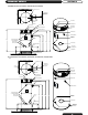
SECTION 3 INSTALLATION TYPICAL PROPANE BULK STORAGE TANK INSTALLATION Fig.1 TYPICAL PROPANE CYLINDER INSTALLATION Fig.2 Important These drawings show a schematic representation only and should not be used for installation purposes. Contact your gas supplier for authorised installation drawings.
INSTALLATION External wiring to the water heater(s) must be installed in accordance with current I.E.E. Regulations for the wiring of buildings and to any Local Regulations that may apply. The ECOflo range is designed to operate from a 230V, single phase supply. The fuse rating is 5 amps. The method of connection to the mains electricity supply should facilitate complete Electrical isolation of the appliance, preferably by use of a fused double pole switch or fused spur box serving only the heater.
POWERED ANODES ON/OFF SWITCH ANODES BK W N L 2 N 1 2 GN/Y 3 230V T.B. W 1 BK N T.B. G W BK M W N.O. GN/Y BL Y IGNITER 230V W W 24V 4 Y 24V TSTAT BK 3 COLL. LIMIT N.C. BLKD EX. P.S. N.C. FLAME SENSOR GN/Y 5 Y GAS VALVE Y BLOWER RELAY COIL R IGNITER RELAY COIL BL BK 4 3 Y HIGH LIMIT BL BL 5 LED W MV1 R FLAME SENSOR GND L1 S1 S2 LED W MV1 1 BK BLOWER RELAY BL Y/BK GND L1 S1 S2 HSI CONTROL FENWAL 35-309-121 BL GAS VALVE COLLECTOR LIMIT BLOCKED EXHAUST P.
INSTALLATION Your Andrews Water Heater is a Balanced Flue Gas Water Heater where all air for combustion is obtained from the outside atmosphere and all flue gases are discharged to the outside atmosphere. The flue system is a single concentric (pipe within pipe) design where the flue products are discharged through the inside flue tube and the combustion air supply surrounds the flue surrounded by the outside pipe. The flue system incorporates both combustion air supply and the flue exhaust.
SECTION 3 INSTALLATION HORIZONTAL Installation Procedure AND VERTICAL FLUE KITS Determine location of flue exit. 1. The Horizontal or Vertical flue kit that has been delivered includes the components as listed below and on page 21. The concentric flue pipe system includes both the flue exhaust (inside pipe) and combustion air (outside pipe). The flue pipe may be cut on the unflared end (end without gasket) as required for the installation. 2.
INSTALLATION SECTION 3 HORIZONTAL FLUE KIT/FITTINGS PACK - 380 LITRE MODELS AWH PART No: B292 SUPPLIED COMPONENTS Part Description Part Number Exhaust outlet tee c/w condense outlet (82500) E860 100mm to concentric exhaust pipe (75413) E865 Air intake tee piece connector (82501) E862 Condense syphon (87436) E863 Horizontal flue terminal, 100/150mm (87990) E236 90º Elbow c/w clamp, 100/150mm (87890) E205 Gas cock - 3/4” BSP C498 Drain valve - 3/4” BSP C381 Drain valve socket - 3/4” BSP C
SECTION 3 INSTALLATION GENERAL Flue terminals must be installed in accordance with the Clean Air Act to ensure the products of combustion are properly dispersed. The drawing on page 25 shows some minimum clearances for the flue terminal, in addition the flue terminal should be positioned where it will not cause a nuisance from noise or from the combustion products accumulating. Please contact Andrews Technical Support Department if advice is needed for a particular installation.
INSTALLATION SECTION 3 The ECOflo uses a concentric flue system, 150mm outside diameter with an inner flue of 100mm diameter. Flue components fit together with silicon sealing rings and the flues are retained with sealing clamps. Each heater can be ordered with either a horizontal or vertical flue kit. Flue assembly instructions are also included.
SECTION 3 INSTALLATION ECOflo 230 & 380 VERTICAL/HORIZONTAL FLUE SYSTEMS
INSTALLATION SECTION 3 R Q Q M L S R D E C G G B F A F S K,N A H P J J G Likely flue positions requiring a flue terminal guard Fig.3 Terminal Positions with Minimum Distance mm A Directly below an opening, air brick, opening window etc. 300 B Above an opening, air brick, opening window etc. 300 C Horizontally to an opening, air brick, opening window etc.
SECTION 3 INSTALLATION FLUE INSTALLING THE HORIZONTAL FLUE TERMINAL SYSTEMS NOTE! The horizontal flue terminal supplied may be used through outside walls up to 600mm (24in) thick. 1. Horizontal flue Terminal (Through the Wall) supplied a) Cut an opening of at least 165mm (6.5in) diameter through the outside for the ECOflo models. b) Slide the flue terminal through the wall opening to the rib closest to the intake air openings of the terminal even with the outside wall.
INSTALLATION SECTION 3 FLUE INSTALLING THE VERTICAL FLUE TERMINAL 2. Vertical Flue Terminal (Through the Roof) a) Determine the exact location where the roof flue terminal will exit the roof, ensuring the flue system clears all obstructions. For pitched roofs, the flue cap must be the distance above the roof line as specified, (300mm to base of Flue Clamp, minimum). The top of the roof terminal may extend up to 760mm (2.5ft) above the roof line as required.
SECTION 3 INSTALLATIONS FLUE SYSTEMS Gasket End Straight End (Ungasketed) Fig.7 Ribs Locked Beneath Gasketed Clamp g) The last pipe section may be cut to fit the distance required to reach the water heater flue connections. If a flue condense tap is specified then install the supplied trap with crimped end into the gasketed end of the elbow (horizontal flue installations) and clamp the condensate tee and elbow together.
INSTALLATION SECTION 3 The following notes are intended to give guidance: Where the heater is to be installed in a room, NO VENTS ARE REQUIRED. Where the heater is to be installed in a COMPARTMENT, permanent air vents are required in the COMPARTMENT at high and low level. These air vents must either communicate with a room or internal space or be direct to outside air.
SECTION 3 INSTALLATIONS AIR SUPPLY IMPORTANT: AND 1. The effective area requirements specified in the table are related to the maximum heat VENTILATION CONCENTRIC input of of the heater(s), and are equivalent to those specified in BS6644. 2. The free area of the grilles should not be less than the size of the recommended ventilation opening. FLUE SYSTEMS 3. The supply of air to a space housing the heater(s) by mechanical means should be; (a) Mechanical inlet with natural extraction.
INSTALLATION SECTION 3 Where extreme conditions of water hardness exist, scale can form in any water heating equipment, especially when the heater is working under conditions of constant heavy demand and at high temperatures. In hard water areas, scale formation can occur in hot water systems and hot water heaters and the higher the temperature and volume of water used, the more problematic the scale build-up can be.
SECTION 3 INSTALLATION WATER The water heater can be fed from a cold water feed cistern or static water tank. CONNECTIONS A safety valve must be fitted as specified in BS 6644 Clause 9. VENTED SYSTEMS The safety valve must be fitted either directly to an upper tank tapping or not further than one metre along the outlet flow pipe of size not less than the safety valve. There must be no valve separating the heater from the safety valve.
INSTALLATION SECTION 3 WATER CONNECTIONS VENTED SYSTEMS Open Vent Stop Valve Overflow Cold Water Feed Hot Water Service Cold Water Cistern Secondary Return Bronze Pump Check Valve Cold Water Inlet Valve Fig.
SECTION 3 INSTALLATION WATER Unvented Systems should be fitted by an Approved Installer. CONNECTIONS The water heater can be used on unvented hot water storage systems with the addition of an Unvented Systems Kit, part number B290 available from Andrews Water Heaters. UNVENTED See Parts List on page 56. The wall bracket assembly (shown below) is available as an SYSTEMS optional extra (AWH Part No - B173). When used in an unvented system, the Andrews Water Heater will supply hot water at a pressure of 3.
INSTALLATION SECTION 3 If higher flow rates are required for the cold water services, a suitable tee fitting should be fitted to the pipework, upstream of item C1. WATER The pipework fitted to the tundish outlet should be one size larger than the outlet pipe of the safety device and should be terminated at a suitable drain. (See Building Regulations 1992 Approved Document G3).
SECTION 4 COMMISSIONING CAUTION! DO NOT OPERATE THE WATER HEATER UNTIL THE STORAGE VESSEL IS COMPLETELY FILLED WITH WATER, WITH WATER RUNNING FROM ALL HOT TAPS. Open the main gas supply cock after all connections to the gas control are completed and test all connections, using proprietary leak detection fluid. Filling the Heater with Water 1. 2. 3. 4. 5. Close the water heater drain valve. Open the cold water supply valve. Open several hot water taps to allow air to escape from system.
COMMISSIONING SECTION 4 The water heater gas/air mixture is adjusted at the factory for the proper mixture for optimum combustion and ignition for the type of gas listed on the rating label. The water heater should operate properly without requiring adjustment with the gas type shown on the rating label. The following is a guide for the correct mixture adjustment settings in case the gas content is different from the rating label or ignition is not satisfactory.
SECTION 4 COMMISSIONING Fig.14 Table 1 2 CO PERCENTAGE Minimum CO2 Maximum C02 EC230/600 10.7% 11.2% EC230/700 10.0% 10.5% EC230/960 9.8% 10.5% EC380/740 10.0% 10.5% EC380/980 9.8% 10.5% EC380/1220 10.3% 10.8% EC380/1400 10.5% 10.8% LEC230/600 11.0% 11.5% LEC230/700 11.0% 11.5% LEC230/960 11.0% 11.5% LEC380/740 11.0% 11.5% LEC380/980 11.0% 11.5% LEC380/1220 11.0% 11.5% LEC380/1400 11.5% 11.
OPERATING INSTRUCTIONS SECTION 5 WARNING Water heaters are heat-producing appliances. To avoid damage or injury there must be no materials stored against the water heater or flue system, and proper care must be taken to avoid unnecessary contact (especially by children) with the water heater and flue system.
SECTION 5 OPERATING INSTRUCTIONS LIGHTING INSTRUCTIONS Fig.
OPERATING INSTRUCTIONS SECTION 5 During the winter season or any cold period, you may desire a higher temperature setting to adjust for the colder incoming water. This adjustment, however, may cause additional condensation to form on the colder tank surface. This does not mean the tank is leaking. During summer months, the warmer incoming water temperatures will benefit the performance of your water heater and reduce the amount of condensation developed.
SECTION 5 OPERATING INSTRUCTIONS When properly installed and adjusted, the heater will require minimal attention. Should it become necessary to completely drain the heater, follow instructions given in Section 4, Commissioning. ECO The heater is equipped with an ECO (Energy Cut-Off) device, fitted to the control (ENERGY CUT-OFF) thermostat. It is a temperature sensitive switch which opens at high temperature, shutting off gas to the burner in an overheat condition.
MAINTENANCE / SERVICE Servicing must be carried out by a properly qualified person. SECTION 6 INTRODUCTION Whilst giving these instructions for the care of the Water Heater, it is recommended that checks are carried out by the installer or local gas service engineer, at least annually. Ensure good ventilation by keeping the heater free of extraneous materials and clear of dust and lint. Keep pipework, flue and tops of heaters clear of any combustible materials.
SECTION 6 MAINTENANCE / SERVICE GENERAL KEEP APPLIANCE AREA CLEAR AND FREE FROM COMBUSTIBLE MATERIALS, PETROL AND OTHER FLAMMABLE VAPOURS AND LIQUIDS. Water heater maintenance includes periodic tank flushing and cleaning, and removal of lime scale. The unit should be inspected and adjusted to maintain proper combustion. Refer to Fig 17 below, “Suggested Maintenance Schedule”. A periodic inspection of the flue installation system should be made.
MAINTENANCE / SERVICE 1. 2. 3. 4. Turn OFF the water heater electrical disconnect switch. Open the drain valve and allow water to flow until it runs clean. Close the drain valve when finished flushing. Turn ON the water heater electrical disconnect switch. SECTION 6 FLUSHING WATER HEATER The water heater must be drained if it is to be shut down and exposed to freezing temperatures. Maintenance and service procedures may also require draining the water heater. 1.
SECTION 6 MAINTENANCE / SERVICE TO REMOVE 1. SEDIMENT AND 2. 3. LIME SCALE 4. 5. 6. 7. 8. 9. Drain the heater. Refer to DRAINING THE WATER instructions in this section. Remove outer cover plate from lower side of water heater jacket. Remove cover and gasket from cleanout opening. Remove lime, scale or sediment using care not to damage the glass-lining. Inspect cleanout plate gasket: Replace gasket if necessary, refer to parts list on page 52. Install gasket and cleanout plate.
MAINTENANCE / SERVICE The storage vessel should be checked and cleaned annually Scale formation in the base of the vessel may occur, particularly in hard water areas and is normally associated with high usage and high water temperatures. It is characterised by a rumbling noise when the main burner is lit. Scale formation in the base of the vessel will affect the efficency of the water heater and reduce the life of the storage vessel.
SECTION 6 MAINTENANCE / SERVICE COMBINED At least twice a year, the temperature and pressure relief valve should be checked to TEMPERATURE/ ensure that it is in operating condition. To check the relief valve, lift the lever at the end of PRESSURE the valve several times. The valve should seat properly and operate freely. RELIEF VALVE If water does not flow, remove and inspect for obstructions or corrosion. Replace with a new valve of the recommended size as necessary.
FAULT FINDING Make sure that water heater is plugged in. SECTION 7 MAIN POWER LIGHT IS NOT LIT When the switch is on, is there 230V between L1 and N on the terminal block? If not, then check for loose wire connections on the “Power Switch Wire Harness.” If connections are ok, then replace the switch. If there is voltage between L1 and N then the light on the switch is burnt out. Replace switch. Make sure that the temperature of the tank is cool.
SECTION 7 FAULT FINDING MAIN VALVE Put your hand on the gas valve - Can you feel it energize? If not, then check the voltages DOES NOT TURN ON at the ignition module across pins MV on the plug GND. If there is 24 VAC problem, then check to see if the “Rectifier Harness” is secure. If it is secure, then replace the “Gas Valve” If you can feel the gas valve energize, check the main gas supply is not in the off position.
PARTS LIST SECTION 8 PARTS LIST AND ILLUSTRATION SECTION
SECTION 8 PARTS LIST AND ILLUSTRATIONS 2 3 4 1 5 6 8 7 9 15 13 12 13 14 12 14 11 10 11
PARTS LIST AND ILLUSTRATIONS SECTION 8 Part Ref. Description Part Number Qty 1 Thermostat Sensor probe E883 1 2 Baffle 4” Flue E881 2 3 Mag. Rod Assembly - 230 C288 1 4 Mag.
SECTION 8 PARTS LIST AND ILLUSTRATIONS 1 4 3 2 5 6 7, 8, 9, 10 11 12 13 14 15 16
PARTS LIST AND ILLUSTRATIONS Part Ref. SECTION 8 1) COMBUSTION SURROUND ASSEMBLY Description Part Number Qty 1 Ignition Control Assembly E885 1 2 Switch Main Power E884 1 3 Potentiometer E889 1 High Limit Thermostat E886 2) COMBUSTION ASSEMBLY Part Ref.
SECTION 8 PARTS LIST AND ILLUSTRATIONS ECOflo Concentric Flue Component List (100/150mm dia.) Ref. Part No.
PARTS LIST AND ILLUSTRATIONS SECTION 8 C5 C4 C8 C2 C3 C1 C7 C6 Unvented System Kit Components ECOflo Unvented System Kit B290 - Parts List Ref. Part No.
Andrews Water Heaters Wednesbury One Black Country New Road Wednesbury, West Midlands WS10 7NZ Tel: +44 (0)121 506 7400 Fax: +44 (0)121 506 7401 Email: andrews@andrews-waterheaters.co.uk Website: www.andrewswaterheaters.co.