MRX 710 / 510 / 310 Audio/Video Receiver OPERATING MANUAL
Anthem, AnthemLogic, ARC, and Paradigm are trademarks or registered trademarks of Paradigm Electronics Inc. © Paradigm Electronics Inc. All rights reserved. The information contained herein may not be reproduced in whole or in part without our express written permission. We reserve the right to change specifications and/or features without notice as design improvements are incorporated. Manufactured under license from Dolby Laboratories.
MRX 710 / 510 / 310 Audio/Video Receiver OPERATING MANUAL
IMPORTANT SAFETY INSTRUCTIONS CAUTION RISK OF ELECTRIC SHOCK DO NOT OPEN CAUTION: TO REDUCE THE RISK OF ELECTRIC SHOCK, DO NOT REMOVE COVER (OR BACK). NO USER-SERVICEABLE PARTS INSIDE. REFER SERVICING TO QUALIFIED SERVICE PERSONNEL The lightning flash with arrowhead symbol within an equilateral triangle is intended to alert the user to the presence of uninsulated “dangerous voltage” within the product’s enclosure that may be of sufficient magnitude to constitute a risk of electric shock to persons.
WARNING: To reduce the risk of fire or electric shock, do not expose this apparatus to rain or moisture. Avoid installing this unit where foreign objects may fall onto this unit and/or this unit may be exposed to liquid dripping or splashing. On the top of this unit, do not place: • Burning objects (i.e. candles), as they may cause fire, damage to this unit, and/or personal injury.
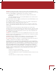
DO NOT LOCATE IN THE FOLLOWING PLACES: To ensure long-lasting use, do not locate the unit: • Exposed to direct sunlight. • Near sources of heat such as heaters. Left 0.2 m (8 in) or more Above 0.2 m (8 in) or more Right 0.2 m (8 in) or more • Highly humid or poorly ventilated. • Dusty. • Subjected to mechanical vibrations. MRX 710 ZONE 2 MAIN • On wobbly, inclined, or otherwise unstable surfaces. • Near windows where there is a chance of exposure to rain, etc.
NOTES ON ENVIRONMENTAL PROTECTION At the end of its useful life, this product must not be disposed of with regular household waste but must be returned to a collection point for the recycling of electrical and electronic equipment. The symbol on the product, user’s manual and packaging, point this out. The materials can be reused in accordance with their markings.
TABLE OF CONTENTS INTRODUCTION ANTHEM ROOM CORRECTION 1 1.1 Before Making Connections 33 4.1 Before Starting 1 1.2 In-Use Notices 33 4.2 ARC Software Installation 2 1.3 Front Panel 34 4.3 Microphone Stand Assembly 3 1.4 Rear Panel MRX 710 34 4.4 Microphone Positioning 4 1.5 Rear Panel MRX 310 34 4.5 Measurement 5 1.6 Remote Control 35 4.6 Manual Mode and Targets 6 1.7 Speaker Positioning 36 4.7 Advanced Subwoofer Targets 37 4.
INTRODUCTION Thank you for purchasing the Anthem MRX series receiver. The MRX 710, MRX 510, and MRX 310 receivers are cutting-edge home theater audio components with HDMI switching, video scaling and upconversion, state of the art room equalization, second zone capabilities, and FM/AM tuner.
1.3 FRONT PANEL MRX 710 shown, others are similar. For a larger diagram see inside back cover.
1.4 REAR PANEL MRX 710 MRX 710 US model shown. EU model, CN model, and MRX 510 are similar.
1.5 REAR PANEL MRX 310 US model shown. EU and CN models are similar.
1.
1.7 SPEAKER POSITIONING The illustrations below show typical 5.1 and 7.1-channel speaker placement. Bass response highly depends on room acoustics and experimentation with subwoofer placement is recommended. Anthem Room Correction can help with placement. 5.1 Channel 7.
CONNECTIONS This section describes connections between system components. Configuration of input and output will be discussed later, in section 3. 2.1 VIDEO CONNECTIONS HDMI With this type of connection, video and audio are carried together digitally. Maximum video resolution is 4K (also known as UHD and 2160p) at 30 frames per second for HDMI outputs and HDMI input 1, and 1080p at 60 frames per second for the rest of the HDMI inputs.
2.2 AUDIO CONNECTIONS AUDIO INPUTS AND OUTPUTS Digital audio sources can be connected with a coaxial, optical, or HDMI cable. These carry 2-channel PCM, Dolby Digital, and DTS. The HDMI inputs also accept up to eight channels of PCM, Dolby Digital TrueHD, DTS-HD, and DTS-HD Master Audio. Audio on the HDMI outputs is 2-channel PCM as this is meant for the TV’s use. HDMI AUDIO RETURN CHANNEL This is meant for use when the TV is the audio source.
SPEAKERS Connect using speaker wire. US models also allow banana plugs. MRX 710 and MRX 510: If you are only using 5.1 speakers in the main zone, the two remaining amp channels may be configured for use in Zone 2, or to bi-amp front L/R in the main zone.
2.3 ANTENNAS To connect the AM loop antenna, press the spring-loaded tabs of the AM ANTENNA connector and insert the bare ends of the two wires. Move the antenna until best reception is found. For the FM antenna, use the FM ANTENNA connector. Later, when unit is operating move the antenna to find best reception. 2.4 LOCAL AREA NETWORK This connection is required for configuring Anthem Room Correction and for using IP control. Connect your router using CAT5 cable or a wireless bridge.
EXAMPLE 1 HDMI IN WAN LAN HDMI IN 2 1 3 WAN 4 LAN 1 2 3 4 HDMI OUT HDMI OUT 11
SETUP For optimum performance and enjoyment, your receiver should be properly set up. This may appear like a lot of work but most settings do not need to be changed from defaults. The important ones relate to your display and input connections, and distance from listening area to each speaker. Anthem Room Correction will set crossovers and channel levels.
3.1 HDMI OUTPUT CONFIGURATION Highlighting HDMI Output Configuration in the main menu then pressing Select displays this menu: HDMI Output Configuration HDMI 1 Color Depth Auto HDMI 2 Color Depth Auto Video Output Auto Video Scaling Processed On-Screen Info Display On HDMI COLOR DEPTH With the default Auto setting, color depth is set to the highest capability reported by the display’s HDMI connection.
3.2 SPEAKER SETUP If your source components also have bass management and time alignment, be sure to disable them by setting all channels “large” and to the same distance from listener since the receiver will be performing these tasks. Audio quality will be degraded if these processes are performed twice.
Speaker Setup Profile Name Center Surrounds Backs Subwoofer Config 1 On On On On PROFILE NAME Using the navigation keys and volume knob each profile can be renamed, up to 8 characters long. When finished, press Select but note that the profile name is best set in Anthem Room Correction (Targets panel) because during file upload the name in the menu is overwritten by the one in ARC. CENTER / SURROUNDS / BACKS / SUBWOOFER If using Anthem Room Correction, these items will be set during measurement.
3.3 BASS MANAGEMENT In this menu, information about your speakers is used so that bass does not become distorted. If using Anthem Room Correction, these items will be set during measurement, so you may skip this menu. If your subwoofer has a crossover, it should be bypassed – set its frequency control to the highest frequency. The bass manager is a crossover that divides audio in two frequency bands suitable for subwoofer/satellite speaker systems.
3.4 LISTENER POSITION Through these settings, sound coming from all speakers is coordinated to reach the listening area at the same time. This way, proper imaging is achieved. The channel with the greatest distance setting will have no delay while channels with shorter distance settings will be delayed accordingly. Distances may be set before or after running ARC (ARC does not set distances). Listener Position Units Config 1 Config 2 feet For measurement units, select feet or metres.
3.5 LEVEL CALIBRATION Level Calibration uses internally generated test noises to match speaker output levels at the listening position. These noises are also a way of checking system connections between receiver, amplifier, and speaker. Audio calibrations from home theater setup discs are not recommended – some use incorrect methods. If using Anthem Room Correction, these items will be set during measurement.
3.6 INPUT SETUP Inputs and listening mode presets are configured in this section. From the factory, 5 inputs are set but you may change this to anything from 1 to 20 configurations. Input Setup HDMI 1 HDMI 2 HDMI 3 FM AM Add Input To add an input at the end of the list, highlight Add Input and press Select. To insert an input, highlight one on the list and press Input. The new input will be inserted after the highlighted one. To delete an input, highlight it and press Clear on the remote control.
INPUT NAME Using the navigation keys and volume knob each input can be renamed, up to 8 characters long. When finished, press Select. Example – Rename “HDMI 1” to “Blu-ray”: • Highlight “Input Name” and press Select. The first character will be highlighted in red. • Use the up/down buttons or volume knob to change “H” to “B”. • Use the left/right buttons to move to each remaining character and complete the renaming.
LISTENING MODE PRESETS A listening mode is processing that enhances source material by increasing the number of output channels. Each mode performs this its own way, providing its own type of sound. To find your preference, spend some time listening to various modes using various sources. To disable presets and make selections entirely on the fly, select “Last Used”. To disable listening modes altogether, select “None”.
FOR 5.1-CHANNEL SOURCES (MRX 710/510) 7.1 speakers are needed in the main zone. Dolby Pro Logic IIx Movie is suitable for extracting back channels from any 5.1-channel source. Dolby Pro Logic IIx Music is similar but with increased emphasis on the surround channels. DTS Neo:6 is also suitable for extracting back channels from any 5.1-channel source.
3.7 VOLUMES / REC OUTPUT Here you can set preferences as listed. Volumes / REC Output Mute Level Main Max Volume Zone 2 Max Volume Main Power On Volume Zone 2 Power On Volume Mute Analog REC Out when selecting Mute Digital REC Out when selecting Silent 10 dB 10 dB -35 dB -35 dB Never Never MUTE LEVEL When Mute is pressed, sound can cut out completely or decrease in volume by the amount that you set to keep some of it in the background. Select from Silent or -5 to -30 dB in 5 dB steps.
3.8 NETWORK / REMOTE CONTROL Network / Remote Control Device Name Network Type IP Configuration Trigger Configuration TCP Port UDP Port Rear IR Front IR Tx Status MRX 710 Wired LAN 14999 14999 Enable Enable Disable DEVICE NAME: This is the name that the receiver broadcasts, and it can be changed using up to 16 characters. NETWORK TYPE: The default is wired LAN, which will allow the easiest way to run Anthem Room Correction, described later, as long as the receiver is connected to an Ethernet router.
IP CONFIGURATION Settings in this submenu should only be changed if your network administrator gives the direction or if using Direct Connect to run ARC. IP Configuration Mode IP Subnet Mask Gateway Auto 192.168.1.3 255.255.255.0 192.168.1.1 MODE Static IP settings take effect once this is changed to Manual. For ARC, enter the IP, Subnet Mask, and Gateway values shown above (note that the receiver’s IP address is not the same as the computer’s).
TCP AND UDP PORT Change these only if there is a conflict with another application that uses 14999. REAR AND FRONT IR This allows you to disable each of the receiver’s infra-red inputs, which can be useful when the receiver is connected to an IR repeater and is receiving too many signals. Note that the moment that you disable the front IR input, you will not be able to control the receiver the traditional way from the remote control – re-enable the IR input using the front panel buttons.
3.9 DISPLAY The front panel display’s brightness is set here. Display Brightness Wake Up Brightness Medium Up 1 BRIGHTNESS: Set preferred default brightness. WAKE UP BRIGHTNESS: When a button is pressed the display can go to a brighter level for 5 seconds – select None, Up 1 brightness level, Medium, or High. When “None” is selected and the display is off, the wake-up behaves as Up 1 to indicate that the unit is running.
3.10 GENERAL CONFIGURATION This menu contains power saving, control, and tuner options. General Configuration Auto Off ECO Mode IP Control Standby IP Control Standby HDMI Bypass CEC Control CEC Power Off Control CEC Power On Control AM Tuner Steps FM Tuner Steps 30 minutes Enable Enable Disable Disable Off Disable Disable 10 kHz 100 kHz AUTO OFF When there is no input signal the receiver will turn off after the selected time: 5, 10, or 30 minutes, 1, 2, or 6 hours, or Never.
CEC When Consumer Electronics Control is enabled it allows controlling one HDMIconnected component using another’s remote control, as long as CEC is also enabled in the other components. Note that when component brands are mixed this control system may not be reliable. CEC Control must also be On for Audio Return Channel, described in an earlier section, to function.
3.11 SAVE / LOAD SETTINGS Save / Load Settings Save User Settings Load User Settings Reset on-the-fly Settings Load Factory Defaults SAVE/LOAD USER SETTINGS After selecting Save User Settings and confirming, all menu settings will be stored. If you change settings later and want to recall the saved settings, select Load User Settings and confirm. RESET ON-THE-FLY SETTINGS After selecting and confirming, all non-menu settings such as level and bass/treble will be reset.
3.12 SYSTEM INFORMATION System Information Update Via USB Release Version Main Micro Version DSP Version HDMI Version ARC Name ARC Upload Time MAC Address LAN Status 1.0.5 1.0.5 0.2.2 0.2.1 7C:B7:7B:00:00:0A Disconnected UPDATE VIA USB AND VERSION NUMBERING: The operational characteristics of the receiver are controlled by software installed through the USB port on the rear panel. Updates can be downloaded from our web site and installed afterwards. • On www.anthemAV.
ANTHEM ROOM CORRECTION ARC corrects the effects of reflective surfaces and room boundaries on sound quality by measuring the response of each speaker relative to the listening area and equalizing it. ARC equalizes response without stressing the amplifier or speakers and does not downsample the source material to process it.
4.1 BEFORE STARTING • Ensure that the receiver software and ARC-2 software that you will be using are compatible with one another – check www.anthemAV.com for latest versions. • Your ARC microphone and its support file are a system. Before a mic can be used for measurement, its response must be known. Each ARC microphone’s frequency response is measured precisely at the factory and this is used to create your microphone’s calibration file.
4.3 MICROPHONE STAND ASSEMBLY Screw the telescoping tube into its base and the microphone clip onto the tube. Position the clip vertically. Connect the USB microphone cable to the microphone and slide the microphone into the clip. 4.4 MICROPHONE POSITIONING During measurement the microphone must point straight up. The microphone’s height is critical to proper measurement and should be at ear level when seated.
4.6 MANUAL MODE AND TARGETS When creating a new file, manual mode is the same as automatic mode except that you must measure, calculate, and upload in separate steps. After the measurement phase, targets can be edited but doing so is recommended only for experienced users. A file created in Automatic mode can be opened in Manual mode to allow target editing. After changing targets, you must click OK when closing the window to apply the settings, then Calculate.
If you did change settings such that a large portion of the bass is being boosted, as would be shown by a wide range of the green corrected curve having higher level than the red measured curve, chances are that your equipment will be stressed more than the sound will improve. There is very little to gain by doing this. Instead, address the real reasons behind the areas which could be improved but are beyond what electronic correction is meant to fix, for example large dips in the in-room response.
SUBWOOFER HIGH PASS FREQUENCY Use this with High Pass Order when manually creating a curve on the lower end of the subwoofer’s response. The left side of the red measured curve is the guideline for shaping the target curve. An attempt to use this as a bottom-end boost to increase low-frequency output is likely to be detrimental to the subwoofer’s performance.
OPERATION 5.1 POWER ON / OFF AND VOLUME Main and Zone 2 have separate power controls. During power-on and power-off a mechanical click is produced from the unit – this is normal. Volume comes on according to setup menu setting. Front Panel ZONE 2 Remote MAIN To control volume rotate the front panel knob or press VOL up/down on the remote control. To mute or un-mute the audio, press MUTE. VOL 5.
5.3 INPUT SELECTION The number of active inputs varies according to how the Input Setup menu was programmed. To scroll through the next/previous active inputs press the right/left buttons, and to make a selection press SELECT. Front Panel Remote SELECT INPUT Alternatively, press the INPUT button for an on-screen list of inputs. Use the up/down and SELECT buttons to change the input. To change input in Zone 2, press the INPUT button (after pressing ZONE button if using the front panel).
PRESETS (remote control only) 30 AM and 30 FM stations can be stored. To store the current station press PRESET then assign a number from 01 to 30. To recall a preset enter the assigned number or press PG/PR up/down for the next/ previous one. To delete a preset, select it then press CLEAR. 1 2 3 4 5 6 7 8 9 PRESET 0 CL EA R PG/PR 5.5 LEVEL TRIM If a channel group, for example the surrounds or the subwoofer, occasionally sounds too loud or soft, its level can be adjusted on the fly.
5.6 BASS / TREBLE / BALANCE To change tone, press Bass or Treble on the remote control then up/down. Note that Bass does not affect the subwoofer output – this is handled by the Level adjustment. BASS BAL TREB To change balance press BAL on the remote then up to move the image to the right, or down to move the image to the left. 5.7 LIP-SYNC If the audio is not synchronized with the video, press Lip-Sync then up/down. Up to 150 milliseconds of audio delay may be used.
5.9 DOLBY VOLUME AND DYNAMIC RANGE CONTROL Refer to the Input Setup section for a description of Dolby Volume. To change on/off status press DYN on the remote control then up/down. To change Leveler amount press DYN a second time when Dolby Volume is on then adjust. DYN When Dolby Volume is off another dynamic range control becomes available after DYN is pressed a second time.
SPECIFICATIONS PREAMPLIFIER Maximum Output (<0.1% THD . . . . . . . 3.5 Vrms, subwoofer channel 6.1 Vrms Frequency Response (2 Vrms output) . . . . . . . . 8 Hz to 28 kHz (+0, -0.25 dB) Frequency Response, Analog-Direct mode (2 Vrms output) . . . . . . . . . 8 Hz to 50 kHz (+0, -0.25 dB) THD+N (2 Vrms output) . . . . . . . . . . . . . . . . . . . . . . <0.03% S/N Ratio (2 Vrms output, IEC-A filter) . . . . . . . . . . .
LIMITED WARRANTY CANADA & USA The warranty period on new Anthem products is: 5 years: Separate power amplifiers and integrated amplifiers 3 years: Audio/Video preamplifiers and receivers Please register your product at www.anthemAV.com The warranty period begins on the date of purchase from Anthem or an Authorized Anthem Dealer. This warranty is offered only to the original owner and is not transferable.
ZONE 2 MRX 710 MAIN THE BIG PICTURE FRONT PANEL (MRX 710) 45
THE BIG PICTURE REAR PANEL (MRX 710) 46
THE BIG PICTURE REAR PANEL (MRX 310) 47
NOTES
NOTES
NOTES
DESIGNED IN NORTH AMERICA +1 905-564-1994 9:00 am - 5:30 pm M-F (ET) www.anthemAV.