
User Guide

7 Page
Installation Manual
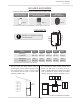
INSTALLATION
GENERAL
1. Follow all local codes, or in the absence of local codes, follow the most recent edition of the National
Fuel Gas Code: ANSI Z223.1/NFPA 54 in the USA or CAN/CSA B149.1 Natural Gas, Propane Installation
Code in Canada.
2. All gas water heaters require careful and correct installation to ensure safe and efficient operation.
This manual must be followed exactly. Read the “Safety Guidelines” section.
3. The manifold gas pressure is preset at the factory. It is computer controlled and should not need
adjustment.
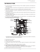
4. Maintain proper space for servicing. Install the water heater so that it can be connected or removed
easily. Refer to the "Clearances" section on p. 9 for proper clearances.
5. The water heater must be installed in a location where the proper amount of combustible air will be
available to it at all times without obstructions.
6. The electrical connection requires a means of disconnection, to terminate power to the water heater
for servicing and safety purposes.
7. Do not install the water heater where the exhaust vent is pointing into any opening in a building or
where the noise may disturb your neighbors. Make sure the vent termination meets the required
distance by local code from any doorway or opening to prevent exhaust from entering a building (refer
to p. 17 to 19).
8. Particles from flour, aerosols, clothes dryers and other airborne contaminants may clog the air vent,
build up and reduce the functions of the rotating fan, cause improper burning of the gas, or cause
damage to the water heater. Regularly ensure that the area around the water heater is dust- or debris-
free. Regular maintenance is recommended for these types of environments. Sealed combustion is
recommended too.
9. The 140 Indoor (T-H3M-DV) model is to be installed indoors only. The model is equipped with a
thermistor and hi-limit switch for the exhaust gas, detecting excess temperatures within the flue and
enabling the water heater to safely stop operation if needed. These components are always monitoring
exhaust gas conditions in order to prevent heat damage to ABS, PVC, CPVC, or Polypropylene (Plastic)
venting if ABS, PVC, CPVC, or Polypropylene is used. If the exhaust gas temperature exceeds 140 °F
(60 °C) these components will enable the water heater to safely stop operation. (These components
are not installed on the outdoor model since the exhaust vent is built-in.)
• The Indoor model requires 3 inch, or 4 inch diameter intake air supply pipe. The intake pipe must
be sealed airtight.
• Air supply pipe can be made of aluminum flexible tube, ABS, PVC, CPVC, Polypropylene,
corrugated stainless steel, or Category lll / IV stainless steel. Regarding exhaust pipe, please refer
to p.11 for detailed information.
• Sidewall venting is recommended for the Indoor model. Vertical venting (roof termination) is
acceptable.
• The manufacturer recommends running the exhaust vent and the intake pipe as parallel as possible.
10. The 140 Outdoor (T-H3M-OS) model is only to be installed outdoors and only in the area with mild,
temperate climates.
The Outdoor model shall be wall-mounted or mounted on a stand. Locate the Outdoor model in an
open, unroofed area and maintain the minimum clearances. (Refer to p.9.)
Installaon