Installation and Operation G-Type Rack Power Filter G50B-20A2 120V 20A
Contents General Information ........................................................ 1 Overview . . . . . . . . . . . . . . . . . . . . . . . . . . . . . . . . . . . . . . . . . . . . . . . . 1 Inventory . . . . . . . . . . . . . . . . . . . . . . . . . . . . . . . . . . . . . . . . . . . . . . . . 1 Safety . . . . . . . . . . . . . . . . . . . . . . . . . . . . . . . . . . . . . . . . . . . . . . . . . . . 1 Components . . . . . . . . . . . . . . . . . . . . . . . . . . . . . . . . . . . . . . . . . . . .
Display Interface Menus. . . . . . . . . . . . . . . . . . . . . . . . . . . . . . . . . . . . 7 Status menu . . . . . . . . . . . . . . . . . . . . . . . . . . . . . . . . . . . . . . . . . . . . . 7 Setup menu . . . . . . . . . . . . . . . . . . . . . . . . . . . . . . . . . . . . . . . . . . . . . 8 Save screen as default . . . . . . . . . . . . . . . . . . . . . . . . . . . . . . . . . . . 10 Troubleshooting ............................................................ 11 Common problems and solutions.
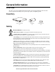
General Information Overview The APC® AV G-Type G50B-20A2 Rack Power Filter protects high-performance audio and video system equipment from damage due to power surges, spikes, and lightning strikes. Inventory Power conditioner (1) Flashlight (1) Stabilizing feet (4) Safety Electrical Hazard: For indoor use only. • Risk of electric shock. Do not plug into another relocatable power tap. • Contains always on receptacles.
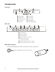
Components Front view Circuit breaker Power button LCD Display SETUP button ALWAYS ON outlet STATUS button DOWN button LED Indicators UP button Removable flashlight av005a Rear view System Ground ALWAYS ON outlets SWITCHED outlet MASTER outlet / DELAY1 outlet CONTROLLED OUTLETS / DELAY 2 (A & B) outlets CONTROLLED OUTLET / DELAY 3 outlet CONTROLLED OUTLET / DELAY 4 outlet Removable Flashlight The removable flashlight can be replaced, contact APC to order a rep
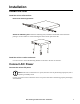
Installation Install the Unit Install the unit on a flat surface Remove the mounting brackets. Attach the stabilizing feet. Attach the stabilizing feet (included) to the bottom of the unit before placing it on a flat surface to avoid scratching the surface and to protect the unit. Install the unit in a rack or enclosure Use four screws to secure the mounting brackets to the rails in the rack or enclosure.
Connect Components to the Unit Power-Saving Master and Controlled outlets The G50B-20A2 reduces power consumption by disconnecting utility power to devices that are not in use. When a device is in sleep or standby mode, it still uses power; when the G50B-20A2 turns off the power to an outlet, it conserves this power. 1. Before connecting components to the unit, determine which components will utilize the Master and Controlled outlets. – Connect a master device such as a TV to the Master outlet.
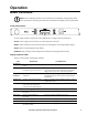
Operation Basic Functions Note: The LCD display interface screen and LEDs can be dimmed, using the Setup menu. Press any button on the front panel of the unit to illuminate the display screen and the LEDs. Front panel buttons Utility Source 122V 60Hz Use the display interface on the front of the G50B-20A2 to configure and operate the unit. Power. Push to apply power to the unit or to shut off power to the unit. Status.
Configure the Unit Set the Language Select a language. Push the SETUP button until the Language menu is displayed. Select English, French, or Spanish. Configure the brightness of the display. To alter the brightness of the LCD display screen, push SETUP one time and select a numerical value, one through seven. Sequence Delay outlets Configure the delay options so that the DELAY outlets apply power in sequence, instead of all at one time. Push SETUP until the delay menu screen appears.
Lock the unit The unit can be locked to prevent unwanted access. To lock or unlock the unit, push STATUS and DOWN for three seconds. G50B-20A2 LOCKED Shut down the unit Push and hold the POWER button. POWERING DOWN Display Interface Menus Status menu The Status menu shows the overall status of the unit and of each outlet on the unit. Push the STATUS button to move to the next screen. Use the arrow keys to scroll up and down. Note: The menus shown in this manual are for reference only.
Contact Information. 1-888-8827228 WWW.APCAV.COM Model and Serial Number. G50B-20A2 SN: AB1234567890 Firmware version. FW REVISION: 880.M1a.D Recent Faults. The screen will either display “No fault” or it will report any recent faults on the unit and give a brief description. Contact APC AV Customer support. NO FAULT FAULT CONDITION Description Setup menu Use the Setup menus to configure the unit. There are nine setup menus. Push the SETUP button to move to the next screen.
Power Threshold. The amount of power used by a device in Sleep or Standby mode varies between devices. It may be necessary to adjust the threshold at which the Master outlet signals the Controlled outlets to shut down. 1. Ensure a master device is connected to the Master outlet. Put that device into Sleep or Standby mode, or turn it OFF. 2. Press STATUS and hold for three seconds. 3. The G50 unit will display now recognize the threshold level of the Master device and save it as the new threshold setting.
Language. Select the language for the display: English, French, or Spanish. Push SETUP to go to the next screen, RESET TO DEFAULT. MENU LANGUAGE: ENGLISH Restore default settings. Select YES or NO to restore the default settings. RESET TO DEFAULT YES Save screen as default To save a screen as the default, push STATUS for three seconds.
Troubleshooting Common problems and solutions The unit will not turn on Probable Cause Solution There is no input power, or insufficient input power from the wall outlet. Use a voltmeter to check the output of the wall outlet. Use a device that is known to work properly to check the outlet. Note: The unit will not turn on if the input utility power is out of the acceptable range. A circuit breaker has been tripped. Check the building circuit breakers and the unit’s circuit breaker.
Specifications Input/Output Input/Output Voltage Input/Output Current Frequency Receptacle Types Number of Outlet Receptacles Dimensions (HxWxL) Nominal 120 V 20 A 50/60 Hz NEMA 5-20R 9 4.34 cm x 24 cm x 43.5 (1.71 in x 9.45 in 17.13 in) 2.4 m (8 ft.
Información general Introducción El Filtro de alimentación para bastidor G50B-20A2 tipo G APC® AV brinda protección para los equipos de sistemas de audio y video de alto rendimiento en caso de sobretensión, picos de voltaje y rayos. Inventario Acondicionador de energía (1) Linterna (1) Pie estabilizador (4) Seguridad Peligro eléctrico: Sólo para uso en interiores. • Riesgo de descarga eléctrica. No conecte a otro enchufe de alimentación reubicable. • Ubicar siempre en los receptáculos.
Componentes Vista delantera Disyuntor Botón de encendido Pantalla LCD Botón SETUP (configuración) Tomacorriente ALWAYS ON (siempre encendido) Botón STATUS (estado) Botón DOWN (hacia abajo) Indicadores luminosos Botón UP (hacia arriba) Linterna desmontable av005a Vista posterior Conexión a tierra del sistema Tomacorrientes ALWAYS ON (siempre encendido) Tomacorriente SWITCHED (encendido) Tomacorriente MASTER (principal) / Tomacorriente DELAY1 (retardo 1) Tomacorrient
Instalación Instalación de la unidad Instalación de la unidad en una superficie plana Retire los soportes para montaje. Coloque el pie estabilizador. Coloque el pie estabilizador (incluido) en la parte inferior de la unidad antes de colocarla sobre una superficie plana, a fin de protegerla y evitar que se raye su superficie. Instalación de la unidad en un bastidor o un gabinete Utilice cuatro tornillos para asegurar los soportes para montaje a los rieles del bastidor o gabinete.
Conexión de los componentes a la unidad Tomacorriente principal y tomacorriente controlado para ahorro de energía El dispositivo G50B-20A2 reduce el consumo de energía al desconectar el suministro de energía de la red pública de los dispositivos que no se están usando. Cuando un dispositivo se encuentra en modo suspendido o en espera, sigue consumiendo energía, y esta se mantiene cuando el dispositivo G50B-20A2 desconecta la alimentación eléctrica proveniente del tomacorriente. 1.
Funcionamiento Funciones básicas Nota: la interfaz y los indicadores de la pantalla LCD se pueden atenuar con el menú Setup (Configuración). Presione cualquier botón del panel delantero de la unidad para iluminar la pantalla y los indicadores. Botones del panel delantero Utility Source 122V 60Hz Utilice la interfaz de pantalla, ubicada en la parte delantera del G50B-20A2, para configurar y poner en funcionamiento la unidad. Encendido. Presione este botón para encender o apagar la unidad. Status (estado).
Indicador luminoso 18 Encendido Apagado DELAY 1 (RETARDO 1) La alimentación eléctrica se está suministrando a DELAY1. La alimentación eléctrica no se está suministrando a DELAY1. DELAY 2A (RETARDO 2A) La alimentación eléctrica se está suministrando a DELAY2A. La alimentación eléctrica no se está suministrando a DELAY2A. DELAY 2B (RETARDO 2B) La alimentación eléctrica se está suministrando a DELAY2B. La alimentación eléctrica no se está suministrando a DELAY2B.
Configuración de la unidad Configuración del idioma Seleccione un idioma. Presione el botón SETUP (configuración) hasta que aparezca el menú Language (idioma). Seleccione English (inglés), French (francés) o Spanish (español). Configuración del brillo de la pantalla. Para modificar el brillo de la pantalla LCD, presione SETUP (configuración) una vez y seleccione un valor numérico, del 1 al 7.
Ver el ahorro de energía y dinero. Consulte el menú Energy Saved (energía ahorrada) en el menú Status (estado) para ver la cantidad de energía que ahorró la unidad. En el menú siguiente, Money Saved (dinero ahorrado), puede ver el ahorro en los costos. Tomacorrientes de detección de corriente La unidad G50B-20A2 puede medir la cantidad de energía utilizada por los equipos que están conectados a los tomacorrientes de retardo.
Energía ahorrada. ENERGÍA AHORRADA 5 KWH Dinero ahorrado. DINERO AHORRADO 0.06 Dollars Contact Information (información de contacto). 1-888-8827228 WWW.APCAV.COM Model and Serial Number (modelo y número de serie). G50B-20A2 NS: AB1234567890 Versión de firmware. REVISIÓN DEL FIRMWARE: 880.M1a.D Fallas recientes. La pantalla muestra el mensaje “Sin fallas” o muestra las fallas recientes de la unidad, acompañadas de una descripción breve.
Atenuador de los indicadores luminosos. Permite configurar el brillo de los indicadores luminosos. ATENUADOR DE INDICADORES: ATENUAR 1 Retardos del 1 al 4. En esta pantalla, se puede seleccionar la cantidad de segundos de retardo para los tomacorrientes de retardo DELAY 1, 2A, 2B, 3 y 4. RETARDO 1: 4SEG (1-60) Límite de energía. La cantidad de energía que utiliza un dispositivo en modo suspendido o en espera varía según cada dispositivo.
Información de contacto. Se puede personalizar esta pantalla para incluir la información de contacto del distribuidor o instalador de A/V. Presione el botón STATUS (estado) para mover el cursor hacia la letra siguiente y utilice los botones Up (hacia arriba) y Down (hacia abajo) para encontrar la letra adecuada. 1-888-8827228 WWW.APCAV.COM Voltajes máximo y mínimo. Configure los límites de voltaje para el funcionamiento normal de la unidad.
Resolución de problemas Problemas comunes y soluciones La unidad no se enciende Causa probable Solución No hay suministro de entrada, o el suministro de entrada Utilice un voltímetro para verificar el suministro de salida del proveniente del tomacorriente de pared no es suficiente. tomacorriente de pared. Utilice un dispositivo que funcione correctamente para verificar el tomacorriente.
Especificaciones Entrada/salida Voltaje de entrada/salida Corriente de entrada/salida Frecuencia Tipos de receptáculos Número de receptáculos de salida Dimensiones (alto x ancho x largo) Cable eléctrico 120 V nominales 20 A 50/60 Hz NEMA 5-20R 9 4,34 cm x 24 cm x 43,5 cm (1,71 in x 9,45 in 17,13 in) 2,4 m (8 ft.
Informations générales Aperçu Le filtre d'alimentation G50B-20A2 pour périphérique audio-vidéo en rack de type G d'APC® est conçu pour protéger les systèmes audio et vidéo haut de gamme contre tout dommage dus aux sautes de puissance, aux pics d'alimentation ou aux coups de foudre. Inventaire Conditionneur d'alimentation (1) Lampe de poche (1) Pied stabilisateur (4) Sécurité Danger électrique : pour l'usage intérieur seulement. • Risque de choc électrique.
Composants Vue avant Disjoncteur Bouton d'alimentation Écran LCD Bouton SETUP (Configuration) Prise TOUJOURS ALIMENTÉE Bouton STATUS (État) Bouton DOWN (vers le bas) Témoins lumineux Bouton UP (vers le haut) Lampe de poche amovible av005a Vue arrière Mise à la terre du système Prises TOUJOURS ALIMENTÉES Prise COMMUTÉE PRISE principale / Prise à DÉLAI 1 PRISES CONTRÔLÉES / PRISE À DÉLAI 2 (A & B) PRISE CONTRÔLÉE / PRISE À DÉLAI 3 PRISE CONTRÔLÉE / PRISE À DÉLAI
Installation Installation de l'appareil Installer l'appareil sur une surface plane Retirez les supports de montage. Fixez les pieds stabilisateurs. Fixez les pieds stabilisateurs (fournis) en-dessous de l'appareil avant de le déposer sur une surface plane afin d'éviter d'endommager la surface et protéger l'appareil. Installer l'appareil dans un rack ou dans un châssis Utilisez quatre vis pour sécuriser les supports de montage aux rails du rack ou du châssis.
Branchement de périphériques à l'appareil Prise principale et prises contrôlées par la prise principale, à économie d'énergie Le modèle G50B-20A2 réduit la consommation électrique en coupant l'alimentation des périphériques non utilisés. Lorsqu'un périphérique est en veille ou en hibernation, il continue de consommer de l'électricité. Par contre, lorsque le G50B-20A2 coupe l'alimentation d'une prise, il réduit la consommation électrique. 1.
Fonctionnement Fonctions de base Remarque : la luminosité de l'écran d'affichage ACL et des témoins lumineux peut être diminuée à l'aide du menu Configuration. Appuyez sur n'importe quel bouton du panneau avant pour illuminer l'écran et les témoins lumineux. Boutons de la façade Utility Source 122V 60Hz Utilisez l'interface d'affichage située à l'avant du G50B-20A2 pour configurer et utiliser l'appareil. Alimentation. Enfoncez ce bouton pour allumer ou éteindre l'appareil. État.
Témoin lumineux Allumé Éteint DÉLAI 2B L'alimentation est fournie à la prise L'alimentation n'est pas fournie à la prise à DÉLAI 2B. à DÉLAI 2B. DÉLAI 3 L'alimentation est fournie à la prise L'alimentation n'est pas fournie à la prise à DÉLAI 3. à DÉLAI 3. DÉLAI 4 L'alimentation est fournie à la prise L'alimentation n'est pas fournie à la prise à DÉLAI 4. à DÉLAI 4. COMMUTÉE L'alimentation est fournie à la prise L'alimentation n'est pas fournie à la prise COMMUTÉE. COMMUTÉE.
Configuration de l'appareil Choix de la langue Choisir une langue. Enfoncez le bouton SETUP (Configuration) jusqu'à ce que le menu Langue (Language) apparaisse à l'écran. Choisissez Anglais, Français ou Espagnol (English, French, ou Spanish). Configurer la luminosité de l'affichage. Pour modifier la luminosité de l'écran LCD, appuyez sur le bouton SETUP (Configuration) une fois et entrez une valeur numérique de un à sept.
Prises à détection de courant Le modèle G50B-20A2 peut mesurer la consommation électrique des équipements raccordés aux prises à délai. Verrouillage de l'appareil L'appareil peut être verrouillé pour empêcher tout accès indésirable. Pour verrouiller ou déverrouiller l'appareil, enfoncez les boutons STATUS (État) et DOWN (Bas) pendant trois secondes. G50B-20A2 VERROUILLÉ Extinction de l'appareil Tenez enfoncé le bouton d'alimentation POWER.
Argent économisé. ARGENT ÉCONOMISÉ 0,06 Dollars Coordonnées. 1-888-8827228 WWW.APCAV.COM Modèle et numéro de série. G50B-20A2 SN : AB1234567890 Version du micrologiciel. MICROLOGICIEL : 880.M1a.D Récents problèmes. L'écran affichera soit « Pas d'erreur » ou il indiquera les problèmes récemment détectés sur l'appareil avec une brève description. Contactez le soutien à la clientèle de APC AV.
Seuil d'alimentation. La quantité d'électricité consommée par un appareil en veille ou en hibernation varie selon les appareils. Il peut être nécessaire d'ajuster le seuil à partir duquel la prise Principale indique aux prises Contrôlées de s'éteindre. 1. Vérifiez qu'un appareil principal est branché dans la prise Principale. Mettez l'appareil principal en hibernation ou en mode de veille, ou éteignez-le. 2. Enfoncez le bouton STATUS (État) pendant trois secondes. 3.
Effacer les informations d'économie. Réinitialisez le compteur affichant la quantité d'électricité économisée par l'appareil. SUPR ÉCO ÉNERGIE OUI Langue. Choisissez la langue d'affichage : Anglais, Français ou Espagnol. Enfoncez le bouton SETUP (configuration) pour passer à l'écran suivant, RÉINIT DÉFAUT. LANGUE DU MENU : ANGLAIS Restaurer les paramètre par défaut. Sélectionnez OUI ou NON pour restaurer ou non les valeurs par défaut. RÉINIT.
Dépannage Problèmes habituels et solutions L'appareil ne s'allume pas Cause probable Solution Pas d'alimentation d'entrée, ou alimentation insuffisante au niveau de la prise d'alimentation murale. Utilisez un voltmètre pour vérifier l'alimentation de la prise électrique murale. Utilisez un appareil qui fonctionne correctement pour vérifier la prise. Remarque : l'appareil ne s'allumera pas si la tension d'alimentation du secteur n'est pas située dans une échelle acceptable.
Spécifications Entrée/Sortie Tension d'entrée/sortie Courant d'entrée/sortie Fréquence Types de prises Nombre de prises électriques Dimensions (HxPxL) Cordon d'alimentation électrique Nominal de 120 V 20 A 50/60 Hz NEMA 5-20R 9 4,34 cm x 24 cm x 43,5 cm (1,71 po x 9,45 po x 17,13 po) 2,4 m (8 pi) à angle droit de type NEMA 5-20P Performance contre les surtensions électriques Filtre contre les interférences électromagnétiques / radioélectriques 50 dB de 150 kHz à 1 MHz, 40 dB à 30 MHz Spécifications des
APC Worldwide Customer Support Customer support for this or any other APC product is available at no charge in any of the following ways: • Visit the APC Web site to access documents in the APC Knowledge Base and to submit customer support requests. – www.apc.com (Corporate Headquarters) Connect to localized APC Web sites for specific countries, each of which provides customer support information. – www.apcav.com APC Audio/Visual Technical Support – www.apc.