Broadband PowerShield® Models: CP16 and CP27 User Manual 990-2366A 04/2006
Chapter 1: General Information The PowerShield® provides a power source for broadband telephony, Fiber-to-the-Home/Premise (FTTH/P), and other direct current (DC) equipment/applications. Safety This manual contains important instructions that should be followed during installation and maintenance of the APC equipment and batteries. It is intended for APC customers that set up, install, relocate, or maintain APC equipment.
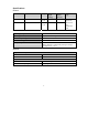
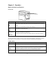
Specifications General Model Number Input Output Maximum Signal Voltage Maximum Signal Current Battery Type CP16U48 100-240 V 50/60 Hz 1.0 A 48 V 16 W 30 V 5 mA CP27U13 100-240 V 50/60 Hz 1.0 A 13 V 27 W 30 V 5 mA 12 V 7.
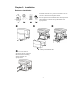
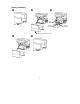
Chapter 2: Installation Enclosure Installation Install the enclosure in a protected area that is free of excessive dust and has adequate airflow. Do not operate the PowerShield where the temperature and humidity are outside the specified limits. See Specifications. Indoor Use Only ! " # Battery Cover Release Tabs $ Use screws that are appropriate for the weight of this unit and the mounting surface material. See Specifications.
Battery Installation ! " # Red Cable Positive Terminal Battery Cover Release Tabs $ % 4 Black Cable Negative Terminal
Connect Equipment and Power The PowerShield battery charges when it is connected to utility power. The battery charges fully during the first eight hours of normal operation. Do not expect full battery run capability during this initial charge period. Utility Power Cord Inlet Output Power and Communication Signals Optional Runtime Extension Connector 1.
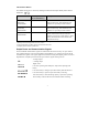
Chapter 3: Operation Status Indicators and Features Front Panel Status Indicators Indicator Description Utility Solid green indicates the unit is on utility power. Solid yellow indicates that utility power is not present and the unit is on battery power. Flashing green LED indicates the unit is fast-charging. Output Green indicates the unit is working properly and DC output power is provided by the battery or the utility power.
Alarm Silence Button The audible alarms may be silenced by utilizing the dual function Replace Battery/Alarm Silence LED/button / . Function Button Operation (Press and hold for:) Description Replace BatteryTemporarily Enable/Disable <4 seconds If the alarm has been silenced, the unit will emit one quick beep. If the alarm has been enabled, two quick beeps will be emitted. Replace BatteryPermanently Enable/Disable 8-12 seconds If the alarm has been silenced, the unit will emit one quick beep.
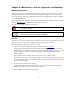
Chapter 4: Maintenance, Service, Approvals, and Warranty Battery Replacement This unit has an easy to replace, hot-swappable battery. Replacement is a safe procedure, isolated from electrical hazards. You may leave the unit and connected equipment on for this procedure. During the self-test, battery removal and replacement are not recommended. For self-test disabling, see Alarm Silence Button. Replace the spent battery with APC replacement battery RBC2. See your dealer or refer to the APC Web site, www.apc.
4. Return the unit by insured, prepaid carrier to the address given to you by Customer Support. Always DISCONNECT THE BATTERY before shipping in compliance with U.S. Department of Transportation (DOT) regulations. Contact Information Refer to the APC Web site, www.apc.com.
Limited Warranty American Power Conversion (APC) warrants its products to be free from defects in materials and workmanship for a period of two years from the date of purchase. Its obligation under this warranty is limited to repairing or replacing, at its own sole option, any such defective products. To obtain service under warranty you must obtain a Returned Material Authorization (RMA) number from customer support.