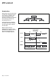
MGETM GalaxyTM 6000 50, 60 Hz 250 - 600 kVA "GTC link" communication interface User manual 125 0 Hour kVA120% 100% 50 Min.
Page 2 - 6739389EN/FB
Contents Presentation ...................................................................................................... 4 Introduction ................................................................................................................ 4 "GTCZ" and "GT2Z" boards features ......................................................................... 4 Communication settings ........................................................................... 5 JBUS protocol ..............................
Presentation Introduction The "GTC link" communication interface is designed to transmit MGETM GalaxyTM 6000 UPS operating information and remote "on/off" commands (if available) to an external computer. The JBUS hexadecimal communication protocol is used (the JBUS ASCII mode is not used in this application). The "GTC link" features two symmetrical communication channels, both with a simplified V24 (RXD and TXD only) and an RS485 interface.
Communication settings The COM1 and COM2 communication ports can be configured as follows: ◗ data rate: 1200, 2400, 4800, 9600 Baud; ◗ data bits: 8 (always); ◗ parity: none, odd, even; ◗ stop bits: 1 or 2; ◗ slave address: 20H to F8H in increments of 8H; ◗ interface: ◗ 0 = RS232 simplified, ◗ 1 = RS232 complete (not implemented), ◗ 2 = RS485; command masks; other parameters (modem type, telephone number, handshaking, modem protocol, password) reserved for later use.
JBUS protocol Introduction JBUS protocol can be used to read or write one or more bits or words. In the interest of simplicity, this document describes only the procedures necessary for operation and monitoring of the APC by Schneider Electric unit. Master request response Slave Slave Slave Communications are initiated by the master and include a request from the master and a response from the slave.
JBUS protocol (continued) Principle A full understanding of the protocol is only required if the master is a computer that must be programmed. All communications include 2 messages: a request from the master and a response from the slave. Each message or frame containes 4 types of information: ◗ slave address (1 byte) The slave address specifies the destination station (see address list): ◗ unitary rectifier-inverter cubicle, ◗ parallel rectifier-inverter cubicle, ◗ Static Switch cubicle.
JBUS protocol (continued) Checking received messages on the slave side After the master sends a request containing the slave address, the function code and data, it computes the CRC and sends it as the check word (CRC 16). When the slave receives the request, it stores the message in memory and calculates the CRC 16 to compare it to the received CRC 16. If the message is incorrect (unequal CRC 16 values), the slave does not respond.
JBUS protocol (continued) Functions Function 1 and 2: read N bits function 1: read output or internal bits; ◗ function 4: read input bits. The number of bits must be less than or equal to the bit field size (see memory board).
JBUS protocol (continued) Function 3 and 4: read N words The number of words must be less than or equal to the word field size (see memory board). ◗ function 3: read output or internal words; ◗ function 4: read input words.
JBUS protocol (continued) Function 6: writing a word request slave address 6 word address word CRC 16 1 byte 1 byte 2 bytes 2 bytes 2 bytes 6 word address word CRC 16 response slave address The response is echoed acknowledging that the word sent has been received.
JBUS protocol (continued) Function 11: reading event counters The master and each slave have one event counter. This counter is incremented each time a frame is received and interpreted correctly by the slave (except for function 11 itself). A correctly transmitted message increments the counter. If the slave sends an exception response, the counter is not incremented.
JBUS protocol (continued) Function 16: writing n consecutive words request slave address 1 byte 10 (*) address of first word 1 byte 2 bytes number of words number of bytes N data bytes 1 byte n bytes 2 bytes CRC 16 2 bytes 2 X 123 4 N 246 MSB LSB MSB LSB MSB MSB LSB last word first word response slave address 1 byte 10 (*) 1 byte address of first word number of words written CRC 16 2 bytes 2 bytes 2 bytes Note: if the slave address is 0, all units execute the write command wi
JBUS protocol (continued) CRC 16 algorithm If the CRC 16 is calculated using the above algorithm, the least significant byte is transmitted first.
JBUS protocol (continued) Example of CRC computation CRC register initialization of 1st character Set flag to 1, Set flag to 1, Shift 1 1111 1111 1111 0000 1111 0010 Shift 1 1111 0111 1010 1111 1111 0000 1111 1111 0000 1101 1110 0001 1 Shift 2 1101 0110 1010 1111 1111 1111 1111 1111 1111 0001 1 Shift 3 Shift 4 1100 0110 0011 101 1111 0111 0011 1111 1111 1111 1110 1111 1111 1 0 1 Shift 5 Shift 6 1001 0100 0010 101 0011 1001 0100 1111 1111 1111 1110 1111 1111 1 0 1 Shift 7 Shi
JBUS protocol (continued) Example of CRC 16 computation in "C" using table lookup #define CPH 0 /* most significant bytes */ #define CPL 1 /* least significant bytes */ /* TABLE OF MOST SIGNIFICANT BYTES FOR CRC16 COMPUTATION */ char tbcrch [ ] = { 0,193,129,64,1,192,128,65,1,192,128,65,0,193,129,64, 1,192,128,65,0,193,129,64,0,193,129,64,1,192,128,65, 1,192,128,65,0,193,129,64,0,193,129,64,1,192,128,65, 0,193,129,64,1,192,128,65,1,192,128,65,0,193,129,64, 1,192,128,65,0,193,129,64,0,193,129,64,1,192,128,
JBUS protocol (continued) */ **************************************************************************************************** */ /* FUNCTION CALL: crc = crc16 (message, length); */ /* with char *message; message = address of message */ /* */ /* int length; length of received message (including CRC) */ /* expressed in number of bytes */ /* int crc; = CRC16 calculated from the "address", "code" and */ /* "information" fields.
UPS theory of operation Unitary UPS The unitary MGETM GalaxyTM 6000 UPSs are made up of five modular sub-assemblies: ◗ ◗ ◗ ◗ ◗ rectifier-charger; battery; three-phase inverter; static switch; maintenance bypass. The load and Mains 2 operate at 50 or 60 Hz. Mains 1 power up the inverter receives power from the rectifier-charger and supplies power to the load. There is no direct connection between Mains and load; ◗ the battery is charged or the charge maintained.
UPS theory of operation (continued) Parallel connected UPS with "Static Switch" cubicle Up to six parallel connected rectifier-inverter cubicles can be combined with one "Static Switch" cubicle to form a system that operates like a unitary UPS system. Each parallel connected rectifierinverter cubicle houses a: ◗ rectifier-charger; ◗ battery; ◗ three-phase inverter. The "Static Switch" cubicle contains: ◗ static by-pass switch; ◗ maintenance bypass.
UPS theory of operation (continued) Operation with battery Mains 1 power up: ◗ the inverter receives power from the rectifier-charger and supplies power to the load. There is no direct connection between Mains 1 and the load. Mains 1 power down: ◗ the inverter runs on battery power and supplies power to the load; ◗ the battery discharges.
Unitary UPS This chapter presents the specific operating aspects and system data provided by the "GTCZ" and "GT2Z" boards in unitary UPSs. For more detailed information, please refer to the "system information" section.
Unitary UPS (continued) Main status bits (UPS operating information) Normal : inverter powers load and full backup time available bit 4C4 = 1 Danger : inverter does not power load bit 4C6 = 1 Downgraded : malfunction or environment fault bit 4C5 = 1 Load on battery : fonctionnement en autonomie bit 4C7 = 1 Operating modes The following section describes the different states of a MGETM GalaxyTM 6000 UPS and the addresses of the bits in the system data array.
Unitary UPS (continued) Load on Mains 2 Normal: Danger: Downgraded: Load on battery: Q1 indifferent: Rectifier/charger indifferent: QF1 indifferent: Inverter disconnected: Q5N closed: Q3BP open: Q4S closed: SS closed: K2S closed (if available): bit 4C4 = 0 bit 4C6 = 1 bit 4C5 = X (N/A) bit 4C7 = X (N/A) bit 40E = X (N/A) bit 408 = X (N/A) bit 400 = X (N/A) bit 484 = 0 bit 498 = 1 bit 497 = 0 bit 496 = 1 bit 499 = 1 bit 494 = 1 Load on bypass Normal: Danger: Downgraded: Load on battery: Q1 indifferent:
Parallel connected UPS This chapter presents the specific operating aspects and system data provided by the "GTCZ" and "GT2Z" boards in parallel connected UPSs. For more detailed information, please refer to the "system information" section.
Parallel connected UPS (continued) Main status bits of system operations Normal : inverter powers load and maximum backup time available bit 4C4 = 1 Danger : inverter does not power load bit 4C6 = 1 Downgraded : malfunction or environment fault bit 4C5 = 1 Load on battery : load on battery power bit 4C7 = 1 Operating modes The following section describes the different states of a MGETM GalaxyTM 6000 UPS and the addresses of the bits in the system data array.
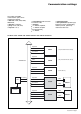
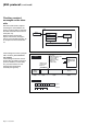
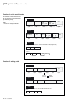
Static Switch cubicle This chapter presents the specific operating aspects and system data provided by the "GTCZ" and "GT2Z" boards for MGETM GalaxyTM 6000 "Static Switch" cubicles. For more detailed information, please refer to the "system information" section. Block diagram Q3BP static by-pass switch (SS and K2S*) Q4S a Mains 2 Q5N inverter 1 inverter 2 load b inverter n * : K2S is the contactor that is parallel-mounted with the static switch on devices with an output greater than 800 kVA.
Static Switch (continued) Main indicators of system operations Normal : charge alimentée par l'onduleur bit 4C4 = 1 Danger : charge non alimentée par l'onduleur bit 4C6 = 1 Downgraded : anomalie de fonctionnement ou défaut d'environnement bit 4C5 = 1 Operating modes The following section describes the different states of a Static Switch cubicle and the addresses of the bits in the system data array.
System information Message format This section describes the messages exchanged between the "GTC link" communication interface and the external computer based on the JBUS protocol. The length of time after which a message must be interpreted as "not understood" depends on the type of command sent.
System information (continued) General definitions object switch unit fault control device 0 open off no fault not activated 1 closed on fault activated Signaling field (same for all cubicle types) signaling units data JBUS address hex.
System information (continued) Voltage fields Legend: ◗ yes: available in this cubicle; ◗ no entry: not available. Power fields Frequency fields Legend: ◗ yes: available in this cubicle; ◗ no entry: not available.
System information (continued) Battery and adjustments fields Legend: ◗ no entry: not available; ◗ yes: available in this cubicle; ◗ bat: available in this cubicle if battery installed; ◗ bat/opt: available if option installed. Inverter type: ◗ 0: unitary; ◗ 1: parallel without static switch; ◗ 2: parallel with static switch; ◗ 3: Static Switch cubicle.
System information (continued) Inverter Legend: ◗ no entry: not available; ◗ yes: available in this cubicle. Connectivity Legend: ◗ no entry: not available; ◗ yes: available in this cubicle; ◗ >800k: on static switch cubicles higher than 800 kVA.
System information (continued) Global information Legend: ◗ no entry: not available; ◗ yes: available in this cubicle; Table of control devices Legend: ◗ no entry: not available; ◗ yes: available in this cubicle.
System information (continued) Glossary of information descriptors (data words at address 40 to 4E) Every bit is listed according to the following format: bit address: description (bit = 0 / bit = 1). Word address: 40 400: battery circuit breaker (0=open/1=closed) Battery protection circuit breaker "QF1" is located near the battery and is "on" (closed) during normal operation.
System information (continued) 41B: battery equalization (0=not active/1=active) The rectifier-charger has been manually switched to equalization mode, to equalize battery cell voltages. This action stops all inverters powered by the battery (if they were not already stopped). 41E: operation on enginegenerator set (0=not activated / 1=activated) Indicates that the rectifier-charger is supplied by an engine-generator set and not by the normal Mains 1 power supply.
System information (continued) Word address: 49 494: contactor K2S (0=open/ 1=closed) Indicates the position of contactor K2S . Contactor K2S is connected in parallel with the static switch on the Mains 2 line on certain high output units. It is installed in staticswitch cubicles with power ratings over 400 kVA. 496: Mains 2 input switch (0=open/1=closed) Switch "Q4S" is located on the Mains 2 phases at the input of the static switch (on the bypass line). The switch is normally closed.
System information (continued) malfunctions: static switch cubicle ventilation fault, ◗ static switch control fault, ◗ environment faults: ◗ battery temperature outside tolerances, ◗ overload exceeding 5%, ◗ Mains 2 voltage, frequency or phase outside tolerances with respect to inverter.
System information (continued) The telephone number is reinstated: ◗ on reception of a new communication configuration using the Soft Tunor after-sales-support computer tool, ◗ when the "GTCZ" or "GT2Z" communication board is deenergised. Word address: C1 C10: call reset (0= not activated / 1=activated) Call reset command issued by the central telemonitoring site. The information bits that provoked the call to the central telemonitoring site are reset.