Model H15 H-Type Power Conditioner 990-2217 Copyright © 2005 American Power Conversion All rights reserved. The APC AV logo is a registered trademark of American Power Conversion. All other trademarks are the property of their respective owners.
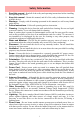
Safety Information 1, 2. 3. 4. 5. 6. 7. 8, 9. 10. 11. 12. 13. 14. 15. Read this manual - Read all of the safety and operating instructions before installing and operating this device. Keep this manual - Retain this manual, and all of the safety information that came with this device. Warnings - Comply with all warnings presented in this manual, as well as any found on the device. Follow Instructions - Follow all operating and use instruction.
Safety Information (continued) 16. Overloading - Do not overload the wall outlet where this device is being connected. Do not overload this device. Ensure the total load to this device does not exceed that which is listed in the Specifications section of this manual. 17. Openings - Do not push any object into the vents provided for cooling, as such an object may come into contact with high-voltage components and cause injury, death, or damage to the device.
Protect Your Investment Thank you for selecting APC's Model H15 Power Conditioner. At APC, we know you have made an intelligent choice sure to reward you for many years. To ensure you receive all the benefits and protection that accompany your purchase, please take a few minutes to fill out and mail the enclosed Warranty Registration Card, or complete the online form at www.apc.com.
iv
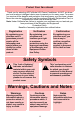
Table of Contents Safety Information i Protect Your Investment iii Introduction 1 Proven Expertise…Proven Reliability 1 Safety Precautions 2 Package Contents 2 Unit Power Capacity 2 Features 2 Automatic Voltage Regulation (AVR) 2 Surge Protection 3 Isolated Noise Filter Banks (INFB) 3 DC Trigger 3 Sequenced Turn ON/OFF 3 LCD Display and Unit Customization 4 Overload 4 Removable Support Feet 4 Front Panel Controls and Indicators 5 Rear Panel Connectors and Circuit Breaker 7 Installation 11 Making Connection
Specifications 17 Troubleshooting 19 Unit will not turn on. 19 The overload LED is lit. 19 “Wiring OK Indicator” LED is not illuminated. 20 The Line Boost and Line Trim LEDs are flashing.
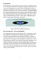
Introduction Congratulations on your purchase of APC’s H15 Power Conditioner (Figure 1). This unit will protect your high performance audio and video (AV) system from damaging power surges, spikes and lightning. Protection is guaranteed. Isolated noise filter banks and Automatic Voltage Regulation (AVR) will eliminate power as a source of audio and video signal degradation. Data-line surge protection jacks will stop surges traveling over phone lines.
Safety Precautions Please ensure you have read and understand all of the safety information located at the front of this manual. If you have any questions about the safety information, or are concerned that your home may not be properly wired for this equipment, please contact APC Technical Support or a qualified and licensed electrician.
Surge Protection The H15 Power Conditioner provides a high level of surge protection for the voltage going into the unit, thus protecting the devices connected to the unit. Additionally, surge protected coax/radio frequency (RF) connectors are protected against surges traveling over coaxial lines to protect your digital satellite system (DSS), CATV box, or cable modem.
LCD Display and Unit Customization The LCD displays important information including voltage in (line voltage) and voltage out, frequency, and load. Additionally, the LCD is used to program features such as the delay or dimmer settings. For convenience, all information provided in the display can be set to English, French, or Spanish. Overload The overload feature is designed to proactively notify the user if the unit and corresponding circuit are overloaded.
Front Panel Controls and Indicators The front panel controls and indicators for the H15 Power Conditioner are detailed in Figure 2. Each numbered callout refers to the numbered description found immediately below the picture. 1 2 12 3 11 4 9 8 10 5 6 7 Figure 2. H15 Front Panel Controls and Indicators 1 Wiring OK Status Indicator When lit, the receptacle into which the H15 is plugged is properly wired.
6 Delayed On Status Indicator When lit, power is ‘on’ at those outlets. 7 Line Trim Status Indicator When lit, the Automatic Voltage Regulation (AVR) is engaged to correct high input voltage conditions. 8 Select Push Button This push button is used to select various setup functions such as: Dimmer, AVR Range, Delay Time, Beeper, or Language (English, French, or Spanish). 9 Backlit LCD Display Provides status information about the equipment plugged into the unit, as well as unit status.
Rear Panel Connectors and Circuit Breaker The rear panel connectors for the H15 Power Conditioner are detailed in Figure 3. Each numbered callout refers to the numbered description found in the following pages. 1 2 8 3 4 7 5 6 Figure 3. H15 Rear Panel Connectors Note: All outlets provide surge protection, voltage regulation, and noise filtering.
1 AC-Powered Outlets The H15 Power Conditioner provides for connection of up to twelve (12) AC-powered devices. The outlets are arranged according to the type of filtering protection provided for a given application. These Isolated Noise Filter Banks eliminate electromagnetic and radio frequency interference that can negatively impact sound and video quality. APC recommends you plug your devices into the outlets as marked, in order to assure optimum protection for your equipment.
3 System Ground Terminal The H15 provides for the connection of grounding wires from all of your equipment to a central terminal lug. This ground connection eliminates ground loop problems; tie all component grounds to this screw to break any possible ground loops that can cause an audible ‘hum’. 4 Circuit Breaker The H15 also provides a “press-to-reset” circuit breaker. When this breaker is “tripped” due to an electrical surge or overload, the device pops out and shuts down output power to the outlets.
7 Surge Protected Telephone Jacks The H15 provides a telephone line splitter with surge protection to protects components connected via telephone line. Connect the supplied RJ11 Telephone cable from the wall jack (source) to the telephone line connector marked “IN”. Connect other telephone cables to the connectors marked “OUT A” and/or “OUT B” and then to the equipment to be protected (Telephone, DVR, DSS, or DSL).
Installation The installation of the H15 consists of the following steps: 1. Making Connections 2. Applying Power 3. Setting Up the H15 Making Connections Note: Whenever the H15 is plugged into a utility AC power source, the microprocessor is active and the unit monitors the input power (standby mode). Prior to connecting equipment to the H15 Power Conditioner, ensure the unit is functional by connecting the AC Power Cord (provided) at the rear panel ( 5 , Figure 3).
Applying Power Apply power to the H15 by pressing the front panel Power Switch ( 9 , Figure 1) fully inward, then releasing the switch. Once power is applied to the unit, the display shown in Figure 4 is illuminated. Vin Vout = = 121 121 Vac Vac Figure 4. Voltage In/Voltage Out Display. Note: In the display shown in Figure 4, the input and output voltages are the same. (The actual voltage may vary depending on the power supplied by your utility.
AVR Range Function - Allows you to adjust the AVR Range of the H15. APC recommends the following settings: • “Wide” if the line voltage in your area is not stable. • “Narrow” if the line voltage in your area is stable (generally around 120V). Press the Setup push button until the “SET AVR RANGE ?” menu is displayed as shown in Figure 6. Then press the Select push button to change the AVR Range setting. After you select the proper AVR Range setting, press the Setup push button to accept the setting.
SET BEEPER Figure 8. Beeper Display Language Function — Allows you to select the language for the LCD display. Repeatedly press the Setup push button to advance to the “SET LANGUAGE” display (Figure 9). Press the Select push button to select the language — English (Figure 10), French (Figure 11), or Spanish (Figure 12). Press the Setup push button to store the setting. SET LANGUAGE Figure 9. Set Language Display LANGUAGE = Figure10.
Using the SELECT Push Button Pressing just the Select push button, allows you to view H15 status information (Power, V out and I out (“I” is the symbol for current), V in and FREQ, Serial Number and Firmware Version), as defined in the following paragraphs: Power — The Power display (Figure 13) displays the power draw (how much capacity, as a percentage (%), is being used by the currently attached load). Power = 0 VA 0% Figure 13.
Serial Number and Firmware Version Display — Pressing the Select push button again will cause the H15 to display the Serial Number of the unit and the current Firmware Version (Figure 16). This information may be required by APC Technical Support, as well as any Warranty claims or Equipment Protection Policy claims. SN: PF0511000123 Version: 0.1B.D Figure 16.
Technical Specifications The following table contains the specifications for the H15.
DC Trigger Two 3.5mm mini-jack plugs (5-30V) CAUTION: When connecting to the DC Trigger jacks, connect the source of the DC trigger to the IN jack. The OUT jack should be used only as a pass-through. The DC Trigger signal can be short circuited if the input and output cables are reversed. The maximum input voltage for the DC Trigger is 30VDC. Do not apply an AC voltage to the DC trigger jacks. Failure to comply with this statement may result in equipment damage. Physical Dimensions (H x W x D) 3.
Troubleshooting This section describes possible causes and solutions for the following problems: 1. Unit will not turn on. 2. The overload LED is lit. 3. “Wiring OK Indicator” LED is not illuminated. 4. The Line Boost and Line Trim LEDs are flashing. Unit will not turn on. Probable Cause: Input power cord is not connected properly. Solution: Ensure supplied power cord is connected firmly at both ends. Probable Cause: No power or insufficient power available at the wall outlet.
“Wiring OK Indicator” LED is not illuminated. Probable Cause: There are 3 reasons why this LED would not be illuminated: 1. Reversed polarity exists at the wall outlet. 2. Neutral wire is overloaded. 3. Earth ground is missing at the wall outlet. Solution: Operating the unit under such conditions may impact its surge protection performance. Contact an electrician to have them inspect the building or home wiring to fix the problem. Probable Cause: Unit is on but LEDs are turned off.