Installation InRow® RD Air Cooled ACRD100 ACRD101
This manual is available in English on the enclosed CD. Dieses Handbuch ist in Deutsch auf der beiliegenden CD-ROM verfügbar. Deze handleiding staat in het Nederlands op de bijgevoegde cd. Este manual está disponible en español en el CD-ROM adjunto. Ce manuel est disponible en français sur le CD-ROM ci-inclus. Questo manuale è disponibile in italiano nel CD-ROM allegato. 本マニュアルの日本語版は同梱の CD-ROM からご覧になれます。 Instrukcja Obsługi w jezyku polskim jest dostepna na CD.
American Power Conversion Legal Disclaimer The information presented in this manual is not warranted by the American Power Conversion Corporation to be authoritative, error free, or complete. This publication is not meant to be a substitute for a detailed operational and site specific development plan.
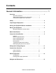
Contents General Information ........................................................ 1 Overview . . . . . . . . . . . . . . . . . . . . . . . . . . . . . . . . . . . . . . . . . . . . . . . . 1 Save these instructions . . . . . . . . . . . . . . . . . . . . . . . . . . . . . . . . . . . 1 Safety symbols that may be used in this manual . . . . . . . . . . . . . . 1 Cross-reference symbol used in this manual . . . . . . . . . . . . . . . . . 1 Safety . . . . . . . . . . . . . . . . . . . . . . . . . . . . .
Installation...................................................................... 14 Removing Doors and Panels . . . . . . . . . . . . . . . . . . . . . . . . . . . . . . . 14 Door removal . . . . . . . . . . . . . . . . . . . . . . . . . . . . . . . . . . . . . . . . . . . 14 Side panel removal . . . . . . . . . . . . . . . . . . . . . . . . . . . . . . . . . . . . . . 14 Positioning the Equipment . . . . . . . . . . . . . . . . . . . . . . . . . . . . . . . . 15 Remove the compressor shipping bracket .
Warranty ......................................................................... 36 One-Year Factory Warranty . . . . . . . . . . . . . . . . . . . . . . . . . . . . . . . .36 Terms of warranty . . . . . . . . . . . . . . . . . . . . . . . . . . . . . . . . . . . . . . . 36 Non-transferable warranty . . . . . . . . . . . . . . . . . . . . . . . . . . . . . . . . 36 Exclusions . . . . . . . . . . . . . . . . . . . . . . . . . . . . . . . . . . . . . . . . . . . . . 36 Warranty claims . . . . . . . . . . .
General Information Overview Save these instructions This manual contains important instructions that must be followed during the installation of this equipment. Safety symbols that may be used in this manual Electrical Hazard: Indicates an electrical hazard which, if not avoided, could result in injury or death. Danger: Indicates a hazard which, if not avoided, could result in severe personal injury or death.
Safety Note: All work should be performed by American Power Conversion (APC®) authorized personnel only. Follow all local and national codes and regulations when installing this equipment. Caution: Keep your hands, clothing, and jewelry away from moving parts. Check the equipment for foreign objects before closing the doors and starting the equipment. Heavy: The equipment is heavy. For safety purposes, at least two people must be present when moving or installing this equipment.
Inspecting the Equipment Your American Power Conversion (APC®) InRowTM RD air conditioner has been tested and inspected for quality assurance before shipment from APC. Carefully inspect both the exterior and interior of the equipment immediately upon receipt to ensure that the equipment has not been damaged during transit. Verify that all parts ordered were received as specified and that the equipment is the correct type, size, and voltage. Filing a claim.
Model Identification The model number can be found on the outside of the shipping crate and on the nameplate located on the rear of the equipment as shown. Use the table below to verify that the equipment is the correct type and voltage.
Component Identification Install kit Note: Do not discard the install kit. The install kit contains items which may be necessary to complete the installation of your equipment. Some items are the literature, floor brackets, and hardware to facilitate joining the equipment to enclosures.
na2625a Exterior components (front) 6 Removable rear door Adjustable leveling foot Side panel latch Display interface Removable side panel Removable front door Rear casters (nonswiveling) Door lock Front casters (swiveling) InRow Air Cooled RD Installation
na2626a Interior components (front) Electrical control box 1 Compressor Electrical control box 2 Front air block panel Temperature sensor (7 total) Evaporator fans (6) Condensate pan floats (2) Expansion valve Condensate pan Evaporator coil InRow Air Cooled RD Installation 7
na2627a Interior components (rear) 8 Filter/dryer Hot gas bypass valve Pressure transducer (2) (located behind air block) Liquid line shutoff solenoid Filter differential pressure port Electrical control box 1 Air filter (2) Power supply unit #2 Condensate pump (2) Power supply unit #1 Electrical contol box 2 Service junction box (top entry shown) Sight glass InRow Air Cooled RD Installation
na2664a Electrical panel Leak detector port Building management system (BMS) RS-485 port Remote temperature sensor port Control RS-485 port A-Link ports Form C and shutdown input Reset button RS-232 console port Network port Outdoor heat exchanger (OHE) ports (optional) InRow Air Cooled RD Installation 9
na2628a Top piping and power access locations Electrical input Liquid line Low voltage wiring inoput Condensate pump outlet Hot gas line na2629a Bottom piping and power access locations 10 Electrical input Condensate pump outlet Low voltage wiring input Hot gas line Liquid line InRow Air Cooled RD Installation
Refrigeration Piping Diagram Liquid Liquid Condenser na2543a Condenser Hot gas RD Top piping Hot gas Bottom piping Receiver Receiver RD Note: Shutoff valves shown nearest to the condensers are not supplied by APC.
Connections Overview All connections to and from the equipment can be made through either the top or the bottom of the equipment. Once the corresponding connectors are sweated or brazed into place, the equipment can be disconnected without soldering, welding, or gluing. See the following tables for information about the sizes and types of connectors. Warning: Make electrical connections in accordance with all local and national codes.
Room Preparation Air distribution The equipment distributes air in a back-to-front discharge pattern, removing hot air from a hot aisle and discharging cooled air into a cold aisle. Note: The equipment is designed for free air discharge or for use with the Rack Air Containment System or Hot Aisle Containment System. The equipment is not intended to be connected to a duct system.
Installation Removing Doors and Panels Door removal Warning: All doors and side panels must be locked during normal operation. Do not open the side panels while the fans are operating. Caution: Use caution when removing the front and rear doors while the equipment is operating. Unplug the display interface cables. na2631a Note: Do not lean the doors against a wall with the side panel latches facing the wall. This can deform the latches and prevent them from properly working.
Positioning the Equipment Remove the compressor shipping bracket Caution: Failure to complete the following steps may result in equipment damage and will void your warranty. The compressor is secured by a bracket to prevent damage during shipping. This bracket must be removed before you apply power to the equipment. 1. Remove two T30 Torx screws from the bracket as shown. Save the screws for possible future use. 2. Remove the bracket and save for possible future use.
Service access A minimum 900 mm (36 in) of clear floor space in front of and behind the equipment is recommended for service. All required periodic maintenance can be performed from the front or rear of the equipment. Most of the cooling components in the equipment (e.g. dry filter, sight glass, solenoid, and expansion valves) must be soldered for repair or replacement. Do not service these components while the equipment is located inside the data center.
Leveling the Equipment Note: The leveling feet at the corners of the equipment provide a stable base if the floor is uneven, but they cannot compensate for a badly sloped surface. 1. Remove the front and rear doors. See “Door removal” on page 14. Note: Before removing the front door, unplug any wires that may interfere with the removal of the doors. na1572a 2. For each leveling foot, insert a Phillips PH2 or slotted screwdriver into the screw above the leveling foot.
Joining the Equipment to Enclosures Joining to SX enclosures The equipment comes with four joining brackets (two for the front and two for the rear). 1. Remove the front and rear doors. See “Door removal” on page 14. 2. Locate the four joining brackets. Rotate each bracket ninety degrees toward the adjoining enclosure so the bracket is parallel to the floor and install using the screws provided with the enclosure.
Mechanical Connections Refrigeration piping The equipment must be connected to a condenser—either a remote outdoor condenser or an indoor centrifugal condenser. Systems with remote outdoor or indoor centrifugal condensers will require discharge and liquid lines from the equipment to the condenser. Install all refrigerant lines in accordance with applicable industry guidelines as well as local and national codes and regulations. To size lines, see “Recommended line sizes” on page 20.
Recommended line sizes Equivalent length m (ft) Line type ACRD100, ACRD101 (OD) 15 (50) Discharge line (horizontal) 5/8 in ACR Discharge line (vertical) 1/2 in ACR Liquid line 1/2 in ACR 30 (100) Discharge line (horizontal) 5/8 in ACR Discharge line (vertical) 1/2 in ACR Liquid line 1/2 in ACR 46 (150) Discharge line (horizontal) 5/8 in ACR Discharge line (vertical) 1/2 in ACR Liquid line 1/2 in ACR Note: All refrigerant pipes must be straight ACR to have 565 psig or above MWP.
Connect refrigerant lines Be sure to use only clean, refrigerant-grade (ACR Type L) pipe and follow standard procedures for pipe size selection for air-cooled equipment. The maximum allowable equivalent length between the evaporator and condenser is 61 equivalent m (200 equivalent ft). Vertical runs (hot gas) require a trap every 6 m (20 ft) of rise.
Condensate pump The condensate pumps are factory-wired and piped internally to the condensate pan. The pumps are capable of moving liquid a maximum of 15.2 m (50.0 ft), which may include a maximum lift of 4.9 m (16.0 ft) as measured from floor level. For example, if your lift is 3 m (10 ft), you only have 12.2 m (40.0 ft) of usable run remaining. The pumps also use on-board condensate high level float switches, which are wired into the alarm input for local and remote alarm capabilities.
Routing the condensate pump drain line. Caution: Failure to properly route condensate drain line before operation could result in water damage. na2671a Top condensate pump drain routing Route the condensate drain line through the top or the bottom of the equipment to an appropriate drain. Note: Comply with all local codes when installing the condensate drain line to the drain system.
Leak sensor (optional) AP9325 na2760a Install one leak sensor (AP9325). To extend the leak sensor length, add up to three additional leak sensors (AP9326). na1584a AP9325 1. Connect the leak sensor to the equipment using the leak detector port as shown. na2676a Leak detector port 2. Position the leak sensor inside or outside the equipment. Note: Install leak sensors on a clean surface, and do not allow them to touch metal that is in an air stream. 3.
Adding a holding charge R-410A is a mixed refrigerant. When charging this equipment with mixed refrigerant, only liquid refrigerant must be charged. Caution: Failure to charge with liquid refrigerant only may damage the system. Note: The equipment must be charged only with R-410A. It is the responsibility of the installing contractor to provide sufficient refrigerant for a complete system charge during startup. Note: It is very important to make a note of the amount of R-410A used in this pre-charge.
Charging Table Condenser Model Selected Condenser Ambient Summer Temperature Charge (lb) Condenser Flooded Charge (lb) for Different Minimum Outdoor Ambient Temperatures 4° C (40° F) -7° C (20° F) -18° C (0° F) -29° C (-20° F) -40° C (-40° F) FCB5 FSC 95° F 4.9 12.1 12.9 13.3 13.6 13.9 FCB5 FSC 105° F 4.9 12.1 12.9 13.3 13.6 13.9 FCB8 FSC 115° F 8.5 21.1 22.4 23.1 23.6 24.1 KH1150.ADV FSC 35° C 3 6.8 7.2 7.4 7.6 7.7 KH1150.ADV FSC 40° C 3 6.8 7.2 7.4 7.6 7.
Electrical Connections The electrical connections required in the field are: • Controls (display interface, Network Management Card) • Communication (A-Link, Building Management System) • Power to InRow RD (single phase plus ground) • Power to flooded receiver heater All electrical connections must be in accordance with applicable industry guidelines as well as national and local codes and regulations. See the equipment nameplate for voltage and current requirements.
User interface connections OHE Shutdown input contacts and alarm output contacts Control na2688a Modbus A-Link ports: Pin 1 = High; pin 2 = Low; Pins 3,6 = Perf Power; Pins 4, 5 = Ground NO (normally open contact) Reset button COM (common contact) Network port NC (normally closed contact) Shield/ground RS-232 console port A- = True OHE (outdoor heat exchanger) alarm input (not used) B+ = True OHE alarm input + (not used) Shutdown - OHE COM (option
Form C alarm contacts and shutdown input Remote disconnect switch na2250a + _ See items 6 through 13 in “User interface connections” on page 28. A relay internal to the user interface is controlled by a user-defined alarm (for example, malfunctioning fans). Before an alarm condition, the signal on the COM (common) terminal is routed to the NC (normally closed) terminal.
Rack temperature sensor gen0744a The rack temperature sensor monitors and controls the equipment airflow and ensures an adequate supply of cooling air to the server racks in the data center. The equipment is supplied with an external rack temperature sensor. See “Install kit” on page 5. This sensor, along with wire clamps and wire clips, are included in the installation kit shipped with the equipment.
A-Link connections The A-Link bus connection allows multiple InRow RD equipment (up to twelve) to communicate with one another. Only one InRow RD must be defined through the display interface; other InRow RDs are numbered automatically. To enable the InRow RDs to work as a group, link them using the supplied cables, or CAT-5 cables with RJ-45 connectors. A terminator (150 Ohm, 1/4 W) is installed in the A-Link port, and must remain inserted into the A-Link ports of the first and final InRow RDs only.
Building Management System (BMS) The Modbus interface allows each InRow RD to communicate with the BMS. Use a three-wire cable to connect each InRow RD in turn. Wire a 150 Ohm, 1/4-W terminator resistor (included) into the MODBUS master and the final InRow RD between Modbus D0 and Modbus D1. Each InRow RD has a three-wire Modbus terminal on the user interface. Use a connector with screw terminals to allow wiring to be attached.
Network port InRow RD # 2 Final InRow RD na2679a InRow RD # 1 Switch/Hub Network port LAN cable (10/100 Base-T) InRow Air Cooled RD Installation 33
Power Connections Wiring configurations Route incoming power to the electrical junction box located at the top or bottom of the equipment. Electrical Hazard: Only a licensed electrician may connect the equipment to utility power. Lock out and tag out all power sources before working with electrical wiring. Do not wear jewelry when working near energized components. Observe all local and national electrical codes.
Connect flooded receiver heater The flooded receiver is equipped with a heater to keep the refrigerant warm during extremely cold weather conditions. The heater requires 208 - 240/1~/60 Hz electrical service to be wired to the condenser electrical panel (see submittal drawings for details). Warning: Make electrical connections in accordance with all local and national codes.
Warranty One-Year Factory Warranty The limited warranty provided by American Power Conversion (APC®) in this Statement of Limited Factory Warranty applies only to products you purchase for your commercial or industrial use in the ordinary course of your business. Terms of warranty American Power Conversion warrants its products to be free from defects in materials and workmanship for a period of one year from the date of purchase.
IN NO EVENT SHALL APC, ITS OFFICERS, DIRECTORS, AFFILIATES OR EMPLOYEES BE LIABLE FOR ANY FORM OF INDIRECT, SPECIAL, CONSEQUENTIAL OR PUNITIVE DAMAGES, ARISING OUT OF THE USE, SERVICE OR INSTALLATION, OF THE PRODUCTS, WHETHER SUCH DAMAGES ARISE IN CONTRACT OR TORT, IRRESPECTIVE OF FAULT, NEGLIGENCE OR STRICT LIABILITY OR WHETHER APC HAS BEEN ADVISED IN ADVANCE OF THE POSSIBILITY OF SUCH DAMAGES.
Warranty Procedures Claims To obtain service under the warranty, contact APC Customer Support (see the back cover of this manual for contact information). You will need the model number of the Product, the serial number, and the date purchased. A technician will also ask you to describe the problem. If it is determined that the Product will need to be returned to APC, you must obtain a returned material authorization (RMA) number from APC Customer Support.
Radio Frequency Interference Changes or modifications to this unit not expressly approved by the party responsible for compliance could void the user’s authority to operate this equipment. USA — FCC This equipment has been tested and found to comply with the limits for a Class A digital device, pursuant to part 15 of the FCC Rules. These limits are designed to provide reasonable protection against harmful interference when the equipment is operated in a commercial environment.
APC Worldwide Customer Support Customer support for this or any other APC product is available at no charge in any of the following ways: • Visit the APC Web site to access documents in the APC Knowledge Base and to submit customer support requests. – www.apc.com (Corporate Headquarters) Connect to localized APC Web sites for specific countries, each of which provides customer support information. – www.apc.com/support/ Global support searching APC Knowledge Base and using e-support.