ESSENCE REVERSE OSMOSIS SYSTEM ROES-UV75-SS INSTALLATION INSTRUCTION & OWNER’S MANUAL Ver 1.0 www.FreeDrinkingWater.
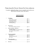
Please keep this Owner’s Manual for future reference. It contains useful information on how to maintain and care for your APEC Reverse Osmosis water filter system. TABLE OF CONTENT 1. Installation: 2. Maintenance: 3. Owner’s Manual - RO Basics: 4. Trouble-shoot Guide: 5. Other Information: 6. Warranty ........................................................................... page 38 Preparation ................................................................... Filter housings assembly .......
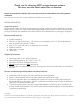
Thank you for choosing APEC reverse osmosis systems. You now own the finest water filter in America. Please read and become familiar with instructions and parts needed before proceeding with the installation. (This manual is constructed for standard APEC Essence ROES-UV75-SS System.) BEFORE INSTALLATION: Inspect the system: Please take the system and all the components out of the box. Inspect the system and all the connection fittings carefully, make sure nothing is damaged during shipping.
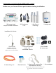
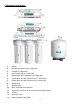
Components included with the ROES-UV75 system: Make sure you have all these parts before starting installation.
Component Itemization: 1) Bracket 2) Membrane and housing (4th-stage filter) 3) UV Light (5th-stage filter) 4) Inline carbon filter (6th-stage filter) 5) Sediment pre-filter and housing (1st-stage filter) 6) Carbon block pre-filter and housing ( 2nd-stage filter) 7) Carbon block pre-filter and housing ( 3rd-stage filter) 8) Storage tank 9) Tank ball valve 10) ASO – Automatic Shut Off valve 11) Check valve (Internal check valve encased in plastic fitting) 12) T-fitting 13) Feed wate
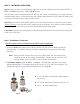
THERE ARE TWO PARTS TO INSTALLING THE RO SYSTEM: Part I. Part II. Note: Assemble the filters and housings onto the main system Installing the system The RO Membrane Element has already been pre-installed. PART I. ASSEMBLE THE FILTERS AND HOUSINGS ONTO THE MAIN SYSTEM Remove plastic/paper wrappings on the 3 filters and housings, put filters into the 3 housings, and assemble the housings onto the main system as follows: Fig. 1 Stand the 3 housings upright.
PART II. INSTALLING THE SYSTEM Space: Make sure there is sufficient space under the counter for installation (an area of about 17”L x 6”W x 18”H for the system, 11”D x 18”H for tank). The RO system is best installed under the kitchen sink. But if that is not feasible you can install the system anywhere where there is a cold water supply with sufficient water pressure for the chosen RO model, and an outlet to drain off the drain water from the system. Mounting: No need to mount the RO system on the wall.
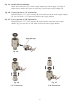
Fig. 4A - Needle Valve Installation. Attach the needle valve (C) to water supply adapter (A). Please apply 4-5 wraps of teflon tape to needle valve prior to connecting it to the water supply adapter (A). Fig. 4B - If your pipe has a 1/2” Connection. By attaching the 1/2” x 3/8” converter (B) to the Male end of the water supply adapter (A), you now have a 1/2” Male and Female water supply adapter. Fig. 4C - If your pipe has a 3/8” Connection.
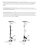
3. Recommend Connection For Flex Line Riser: See Fig. 5A. & Fig. 5E Loosen nut and separate cold water riser tube from shut off valve. Gently bend riser tube so that the Feed Water Adapter (Fig. 4) fits onto the shut off valve. Connect the riser tube, feed water adapter, and shut off valve together and tighten. For Solid Copper Riser: See Fig. 5B. Follow the same procedure as for flex line. If the copper riser cannot bend, this it’s best to replace it with a flex line riser.
Insert Sleeve Compression Nut Push the tubing all the way into the needle valve while tightening compression nut. Apply Teflon Tape Here Fig. 5C Fig. 5D 4. Needle Valve: See Fig. 5D. Screw the Needle Valve onto the Adaptor tightly. Apply 6-8 rounds of Teflon tape onto Needle Valve before attaching it to the Adaptor. To open needle valve: To close needle valve: Turn needle handle counter-clockwise. Turn needle handle clockwise. 5.
Test for leaks after the system is completely installed: Close the Needle Valve (turn needle handle clockwise all the way in to close). Turn ON the cold water supply to the sink faucet. If the Needle Valve or the Adaptor leaks, check the connection and try applying more Teflon tape or tighten the brass nut some more to stop the leak.
3. See Fig. 8, 8A. Make sure to align the drain saddle hole to the drilled hole perfectly. Mis-aligning these two holes will block the drain water and cause membrane damage. Attach the drain saddle to the drain pipe and tighten the two screws evenly. 4. Once the drain saddle is secured, push 1/4” black drain tubing into the Quick Connect fitting on the saddle. DO NOT use a “Insert” on the drain tubing. Fig. 8A Step 3: Drill A Hole For The RO Faucet Drill 1/2” diameter hole for standard RO faucet.
3. For Porcelain Sink: Porcelain enameled sinks can readily be chipped if care is not exercised when drilling the hole. Before starting the drill motor, apply firm downward pressure on the bit until a crunching occurs. This will help keep the drill bit from walking when starting the hole. A small pilot hole will also aid the drill bit. Note: Immediately after the hole drilling is done, clean up all metal chips, for metal chips will stain the porcelain!! Step 4: Mounting The Faucet 1.
Option: Mounting The Faucet (Metal Compression Fitting) 1. Make sure the tube insert is pushed all the way into the tubing. Fig. 9C 2. Make sure the tubing is inserted inside the faucet stem at least 1/4” deep while screwing the nut. Fig. 9D Faucet stem Sleeve & Tube insert Compression nut Counter Top Faucet Base Fig.9D Counter Top Opening Tube insert Black Locating Washer Lock Washer Lock Nut Insert Sleeve Sleeve Compression nut Compression Nut Tubing Fig.
Step 6: Connecting The System IMPORTANT INSTALLATION NOTICE! H The Quick connect fittings come with an end plug that needs to be removed before the tubing can be connected. Please disconnect the end plugs at Points G and H from the Quick connect fittings before connecting tubing. See Fig.10A and Fig.10B. G Fig.10B Fig.10A Depending on your system model, there will be 2 types of protective end plugs. Both types of end plugs are disconnected the same way.
To Disconnect the Tubing: See Fig.10B. Push in and hold down on the collet ring square against the fitting. With the collet held in this position the tube can be removed. See Fig.10E. Fig.10E Summary of Tubing Connections: There are 4 connections: See Fig. 11. & Fig. 11A. Point A to X: Connect RO to COLD water supply — Red tubing. Point G to Y: Connect product water from 5th-stage UV Light to tank — Yellow tubing. This tubing is a 2-way line, Product water enters and leaves the tank via this line.
Option 1 Diagram DRINKING WATER FAUCET Z SINK INPUT WATER TO ICEMAKER OPTION WASTE WATER W Fig.
3. Point W - Drain water connection: Tubing color: Black tubing. Connect the BLACK tubing from the RO to the Drain Saddle. Fitting type: Simply push the Clear tubing into the Quick Connect fitting. No Inserts, Sleeves or Nuts are needed to secure the connection. No Teflon tape needed here. 4. Point A - System water inlet (to Stage 1 pre-filter) connection: Tubing color: Red tubing. Connect the RED tubing from the Feed Water Valve to the RO’s stage -1 prefilter. Fitting type: Quick Connect fitting See Fig.
Install UV BULB into UV Light: 1) Please connect UV bulb to transformer. Fig. 13A 2) Connect the UV bulb pins to the transformer (Fig. 13A) 3) Insert the UV bulb all the way into the UV light securely and make sure the transformer fully covers the UV light bulb entry point (Fig. 13B & Fig.13C) Fig. 13B Fig. 13C Congratulations! You have successfully completed the UV bulb installation. Please continue to Step 7 (Page 18) to system start-up.
Step 7: System Start-Up 1. Turn on feed water: Slowly, turn on your Cold water supply. Open the Needle Valve (turn counterclockwise) to allow the raw water to enter the system. Check for leaks! 2. Open tank valve: Open the tank’s ball valve to allow water to enter the tank. The tank’s valve is “On” when the valve handle is parallel (in the same direction) with the valve’s outlet (see Fig. 12). Check for leaks! 3. UV Light: Please attach the UV Transformer to the UV light, then to power outlet.
ESSENCE RO SYSTEM MAINTENANCE SCHEDULE The system requires very little maintenance. Just change the filter cartridges regularly as suggested below. Keep the system indoors away from extreme hot or cold temperatures, and run the system within its reasonable output capacity (i.e. allow the system to rest at least a few hours a day). To ensure the longevity and integrity of your drinking water system, please use genuine APEC Water replacement filter at www.freedrinkingwater.
3) Discard 3 used filters, wash housings with mild soap, rinse off. Put 3 new filters into their respective housings: sediment filter in stage-1, carbon block filters in stages 2 & 3. 4) Close up the housings. Make sure each housing has a black O-ring in the thread groves. First hand tighten the housing, then use filter wrench to fully tighten each housing. 5) Turn ON the cold water supply with the tank ball valve CLOSED with RO faucet lever turned on.
5) Close the housing cap. Reconnect the WHITE tubing to the cap. Turn on the cold water supply and tank valve. Let the RO system run to re-fill the tank (takes about 2-3 hours). 6) Check for leaks! 7) Drain the first tank of water (through faucet) to flush out the new membrane! The 2nd tank of water is ready for use. K H J Fig. 15C How to Replace Stage-6 Carbon Filter: Replace this last filter at the same time you replace the stage-4 membrane. 1) Remove the OLD filter: See Fig. 15C.
How to Replace Stage-5 UV Bulb: Replace the UV light bulb after 1 year of service. After 12 months, the UV bulb loses its strength. Pro-longed use after 1 year will result in less than optimal performance. 1) Unplug the light Transformer from the power outlet. 2) Do not open the UV light housing. 3) Remove the UV transformer cover from the UV light housing. (Fig. 15D). 4) Remove the old UV bulb from transformer cover and install the new bulb (Fig. 15E & Fig.
OWNER’S MANUAL Please read this section for useful RO system and maintenance information. TABLE OF CONTENT Part I: RO Basics Basic terms ................................................................................. page 24 System flow diagram ................................................................... page 24 Water pressure -- The most important factor ............................... page 25 Tank -- Fill up time. Fill up volume. Delivery pressure ...............
Part I: RO BASICS This section provides basic concepts on how an ROES system works, how it performs in relation to your house’s water condition. We hope this information helps keep your ROES system running at top performance for years to come.
3) Water Pressure – The Most Important Factor! RO systems run on water pressure. Therefore your water pressure has the most direct effect on how well your RO will perform. With sufficient water pressure (85 psi max.), your RO system will function well, give high output with high removal rate, and fill up the storage tank quickly. 4) TDS Meter (Option) – How to Test Your Water Quality: The TDS meter is used to test your water’s quality before and after the RO system.
6) How Full Can My Tank Fill Up? Your water pressure and temperature will determine how full and how fast the storage tank will be filled up. The stronger your input water pressure, the faster and fuller the tank can fill. If water pressure is low, the tank will fill slower and will not fill up to its full capacity.
11) Premature Membrane Failure: There are 4 common causes that lead to premature membrane failure: 1. Failing to replace the 3 pre-filters as frequently as needed: If you’re on city water: The over-depleted carbon pre-filters allow the chlorine to get through and damage the membrane. If you’re on private well water: The overloaded pre-filters allow excessive sediments and particles to get through and clog up the membrane surface. 2.
Part II: Trouble-Shoot Guide For Newly Installed RO System After installation, if you encounter any of the problems described below, please follow this guide to troubleshoot. In most cases, the problem is quickly solved by following this guide. ROES-UV75 System’s Head Diagram Red Tubing From Water Source Fig.
1) Air Bubbles: Lots of Air bubbles in cup or bottle when filling It is quite normal to see air bubbles in a cup of pure water. This mainly occurs when a RO unit is first installed or when filters are being replaced. When new filters are installed to the unit, the filter housings are dry. When they are attached onto the RO head, air pockets will fill the housing. As water is turned on and flows through the unit, the air pockets move throughout the system.
2) Sluggish Flow At Dispensing Faucet - Insufficient water pressure (see “RO Basics” for explanation) —> Check water pressure. If too low for this chosen RO model, either increase your water pressure or add pump to RO system. - Input water to RO is blocked —> Make sure Feed water valve is fully opened and unhindered. - Tank not filled yet —> Wait until tank is more filled, takes 2-3 hours average. - Low tank pre-charge pressure —> Raise tank pre-charge to 5-7 psi.
Step 3. Re-attach the filter housing to the RO head. Hand tighten the housing, then use the filter housing wrench and simply give an additional quarter inch turn. Do Not over tighten the housing. Step 4. Open the tank ball valve and feed water line. Check for leaks. If the filter housing continues to leak, please contact APEC technician for replacement assistance.
7) There is a leak at the Tank ball valve connection If you are experiencing a leak from where the tank ball valve attaches to the tank stem, you may not have applied enough Teflon tape to the stem when you first installed the valve. To correct this issue, please turn off the supply water to the system and turn on the drinking water faucet to completely empty the tank. Then, unscrew the tank ball valve and apply 6-8 wraps of Teflon Tape to the tank stem and screw on the tank ball valve back onto the tank.
10) How to Test RO’s Shut-Off Function: The RO system should shut off automatically when the tank is filled. When the RO fails to shut off after tank is filled, the drain water will keep running down the drain, depleting the pre-filters and membrane. See Fig. 17 Page 28. The Auto-Shut-Off (ASO) valve is located at point C. The Check Valve is located at point E. These two valves control the RO’s shut off function.
Test#2: Test Check Valve and ASO valve: - Make sure there is some water in the tank (tank not empty). - Remove the Black drain line from the drain saddle (so you can check drain flow drainage). - Turn OFF the Cold feed water supply. - Turn ON the tank valve. - Check the Black drain line to see if there is any water draining out from this line. - If water does drain out from the black line --> Then this water is coming from the storage tank.
12) RO Makes Humming Noise When RO makes a humming noise, most likely it’s caused by air bubbles being trapped in the “Check Valve” during installation. See check valve on Fig. 18, point E (Page 29). To purge air from the check valve, do as follows: Step 1: Close the tank’s valve. Step 2: Tilt the RO system to the right. Put something under the 3rd filter housing to keep RO tilted. This helps dislodge the air bubbles from the Check Valve. Step 3: Turn on the RO spigot.
OTHER INFORMATION AirGap Faucet Installation (Optional) There are 3 colored tubings on your Air-Gap faucet. At the end of each 1/4” tubing there is a “Quick Connect” fitting. The Quick Connect fittings is used to connect the Pure and Drain water line from the RO unit to the Air Gap Faucet. To connect the lines, simply insert each line into the fitting port tightly. Fig. 20 Fig. 21 Hook-Up: 1.
How discharge water is disposed via Air-Gap faucet: Discharge water is routed through the Air-Gap faucet prior to being drained off into the standard drainpipe outlet. The 1/4” BLACK waste water line from the RO system will discharge through the 1/4” RED line to the Air-Gap faucet. The drain water will then flow back down the 3/8” BLACK discharge water line of the Air-Gap faucet to your drain pipe.
LIMITED PRODUCT WARRANTY Scope APEC takes pride in selling a superb line of products, including this reverse osmosis system (“Product”). As such, APEC expressly warrants to the original purchaser that, for a period of one (1) year from the date of purchase, the Product will be reasonably free of defects in materials and workmanship.
CONDITIONS THAT RENDER THIS LIMITED PRODUCT WARRANTY VOID THIS LIMITED PRODUCT WARRANTY SHALL BE VOID IF: 1. The Product is not operated in compliance with normal municipal water conditions for which the particular model of this Product is intended. 2. The person seeking to invoke the warranty is not the original purchaser. That is, this Limited Product Warranty only extends to original purchasers. 3. The product is purchased used. That is, this Limited Product Warranty only covers new products. 4.
Advanced Purification Engineering Corp. 1320 S Johnson Drive City of Industry, CA 91745 For questions or comments please visit our website at: www.FreeDrinkingWater.com For technical support contact us at: Techsupport@freedrinkingwater.