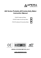
400 Series Portable pH/Conductivity Meter Instruction Manual PH400 Portable pH Meter EC400 Portable Conductivity Meter PC400 Portable pH/Conductivity Meter APERA INSTRUMENTS, LLC www.aperainst.
Table of Contents 1 Brief Introduction ....................................................................................................................................... - 3 Measuring Parameters...................................................................................................................... - 3 Features and Functions .................................................................................................................... - 3 Features in pH Measurement ...................
1 BRIEF INTRODUCTI ON Thank you for purchasing Apera Instruments 400 Series Portable pH/Conductivity Meters. Before using the product, please read this manual carefully to help you properly use and maintain the product. For technical support, please contact us at info@aperainst.com or +1 (614)-285-3080 Apera Instruments reserves the right to update the content of this manual without giving prior notices.
2 TECHNI C AL SPECIFIC AT IONS Parameter Specifications Technical Parameters pH mV Conductivity Temperature Measuring Range (0 to 14.00) pH Resolution 0.01 pH Accuracy ±0.01 pH ±1 digit Temperature Compensation Range (0 to 100) °C, Automatic or Manual Measuring Range -1000 mV to 0 to 1000 mV Resolution 1 mV Accuracy ±0.2% F.S ±1 digit Measuring Range Conductivity: 0 to 200 mS/cm, including 5 ranges: (0.00 to 19.99) μS/cm, (20.0 to 199.9) μS/cm, (200 to 1999) μS/cm, (2.00 to 19.
3 INSTRUMENT DESCRIPTI ON LCD Display ① — Measuring parameters ② — Measuring value ③ — Reminder icons ④ — Measurement unit ⑤ — Temperature unit ⑥ — Measuring unit in calibration ⑦ — Calibration value, numberings of data storage, and reminder icons ⑧ — Temperature and reminder icons ⑨ — ATC—Auto Temperature Compensation; MTC— Manual Temperature Compensation ⑩ — Stable reading icon ⑪ — Completed calibration icons ⑫ — Auto-Lock reading mode ⑬ — Low battery reminder.
Keypad Figure-1 3.2.1 Short Press — <1.5 s;Long Press — >1.5 s 。 3.2.2 Power On: Short press to power on: LCD displays the measuring mode used last time (Backlight turned on for 1 minute). 3.2.3 Power Off: The meter can only be turned off in measuring mode by short pressing Special Notes: Pressing Users need to press in calibration mode or parameter setting mode will NOT turn the meter off. first to go back to measuring mode, and then press to power off.
• Short Press or Long Press • In manual temperature compensation (MTC) mode: Short press to adjust temperature, long press to adjust swiftly. In parameter setting mode: press to change the numbering of parameters in main menu and sub-menu. • In sub-menu, press to change parameters and settings. Connectors The meter adopts 8-pin connector, into which pH, ORP, and conductivity electrode can be connected. When connected, the meter will automatically switch to the correspondent measurement mode.
Table-2 pH Standard Calibration Solution Series Calibration Icons 3-point calibration USA Series NIST Series 4.00 pH 4.01 pH 7.00 pH 6.86 pH 10.01pH 9.18 pH 4.2.2 pH Calibration Modes The instrument has 1 to 3 points auto calibration mode. The 1st point must be 7.00 pH (or 6.86 if using NIST). Then choose other calibration solutions to conduct 2 nd and 3rd points (see Table-3 for details). In the process of calibration, the meter will display the electrode’s slope in acid and alkaline ranges.
pH Calibration (Take 3-point calibration as an example) 4.3.1 Press to enter calibration mode. CAL1 icon will flash in the upper right corner of the LCD. 7.00 pH will flash in the lower right corner of the LCD, reminding you to use pH 7.00 buffer to conduct 1st point of calibration. 4.3.2 Use distilled water to rinse off electrode and then dry it. Dip it into pH 7.00 buffer solution, stir gently and let it stand still and wait for the reading to become stable.
Sample Measurement 4.4.1 Rinse the pH electrode in distilled water, dry it, and dip it into sample solution. Stir the solution gently and let it stand still in the sample solution until icon appears and stays on LCD, get the pH reading, which is pH value of sample solution, please refer to Figure-5 for calibration and measurement process of the pH meter. Figure-5 Calibration and measurement process of pH meter Press to turn on the meter. Press key to enter the calibration mode.
Returning to factory default setting is to restore the meter to the theoretical value (zero potential pH is 7.00, slope is 100%), and set all the parameters to default settings (see appendix 1). When the meter’s calibration or measurement is performing abnormally, users can use this function to let the meter return to factory default mode, and conduct calibration and then test again. Please note that this function is irreversible once used. Maintenance of the pH Electrode 4.5.1.
Inorganic metal oxide Dilute acid less than 1mol/L Organic lipid Dilute detergent (weak alkaline) Resin macromolecule Dilute alcohol, acetone, ether Proteinic haematocyte sediment Acidic enzymatic solution (saccharated yeast tablets) Paints Dilute bleacher, peroxide Notes: 1) The instruments will NOT give accurate and stable pH readings when measuring distilled or deionized water. This because distilled and deionized water do not have enough ions present for the electrode to function properly.
electrode: (a) For inorganic pollutant, soak the electrode in 0.1mol/L dilute hydrochloric acid for 30 minutes, then wash it in distilled water, then soak it in the 3M KCL storage solution for 6 hours. (b) For organic or lipid pollutant, clean the platinum surface with detergent, then wash it in distilled water, then soak it in the 3M KCL storage solution for 6 hours.
Table-8 Conductivity Calibration Solutions Calibration Icons Calibration Solutions 84 μS/cm 1413 μS/cm 12.88 mS/cm 111.8 mS/cm 6.2.2. How often to calibrate (a) The meter has been calibrated before leaving the factory and can generally be used right out of the box. (b) Normally perform calibration once per month. (c) For high accuracy measurements or large temperature deviation from the reference temperature (25°C), perform calibration once per week.
Conductivity Calibration 6.3.1. Rinse the electrode in distilled water, allow it to dry, wash with a little of standard solution and dip it in standard solution. Stir the solution briefly and allow it to stay in the solution until a stable reading is reached. 6.3.2. Press key to enter the calibration mode. The meter’s display will show blinking “CAL” at the top right, and scanning and locking process of calibration solution at the bottom right.
Sample test 6.5.1. Rinse conductivity electrode in distilled water, dry it, and dip it in the sample solution. Stir the solution briefly and allow it to stay in the sample solution until a stable reading is reached and icon appears on LCD, then get the reading value, which is the conductivity value of the solution. 6.5.2. Press key to switch to TDS. 6.5.3. During the process of calibration and measurement, the meter has self-diagnosis functions, indicating the relative information as below: Table – 11.
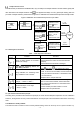
7 PAR AM ETER SETTI NG Main Menu In the measurement mode, press key to enter in P1.0, then press or to switch main menu: P1.0→P2.0→P4.0. Please refer to Figure - 7. P1.0: pH parameter setting menu, P2.0: Conductivity parameter setting menu, P4.0: Basic parameter setting menu. Sub-Menu 7.2.1 In P1.0, press to enter the submenu P1.1 for pH setting, press and to change submenu: P1.1→P1.2→ … →P1.5. See Figure-7 for details. 7.2.2 In P2.0, press to enter the submenu P2.
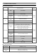
Main Menu pH Setting Submenu P1.1 Select pH buffers P1.2 Restore to factory default Conductivity Setting Submenu P2.1 Select electrode’s constant P2.2 Select reference temp. P2.3 Adjust temp. coefficient P2.4 Adjust TDS factor P2.5 Restore to factory default Basic Parameter Setup Submenu P4.1 Select temp. unit P4.2 Select lasting time for backlight P4.3 Select auto power-off time P4.
pH Setting Sub-Menu P1.1 — Select pH buffer series (USA—NIST) 1. In measurement mode, long press to enter P1.0, press 2. Press , “USA” flashes; Press USA—USA NIS—NIST 3. Press to enter P1.1 to choose USA→NIST; Press to enter P1.2, or press to confirm. to return to measurement mode. P1.2 — Return to factory default mode (No—Yes) Press , “No” flashes, press to choose No→Yes; Press to confirm, the meter returns to measurement mode.
P2.5 — Return to factory default mode (No—Yes) Press , “No” flashes, press to choose No→Yes; Press to confirm, the meter returns to measurement mode. No— not return to factory default mode; Yes—return to factory default mode If not choosing Yes, press to return to measurement mode. Basic Parameter Setting Sub-Menu P4.1 —(°C—°F) 1. Press confirm. , “°C” flashes, press 2. Press to enter P4.2, or press , “°F” flashes; when parameter flashes, press to to return to measurement mode. P4.
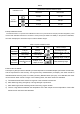
8 9 COMPLETE KI T Content Quantity PH400 EC400 1 PH400 Portable pH Meter 1 √ 2 EC400 Portable Conductivity Meter 1 3 PC400 Portable pH/Conductivity Meter 1 4 201T-S Plastic 3-in-1 Combination pH Electrode 1 5 2301T-S Plastic Combination Conductivity Electrode 1 6 pH Standard Buffer (4.00 pH,7.00 pH,10.01pH/50mL) 1 for each 7 Conductivity Standard Solutions (84μS,1413μS,12.
10 APPENDIX 1: TABLE OF PAR AM ETER SE TTI NG AND FACTORY DEFAULT SETTI NG Mode Symbol Parameter P1.0 P1.1 pH Abbreviation Content Factory Default Select Buffer Series USA-NIST - P1.2 Restore to factory default settings No-Yes No P2.1 Select electrode’s constant 1.0-10.0-0.1 1.0 P2.2 Select reference temperature 15℃ - 30℃ 25℃ P2.3 Adjust temperature compensation coefficient 0.00 - 9.99 2.00 P2.4 Adjust TDS factor 0.40 - 1.00 0.71 P2.
NIST Series Off On No Yes 12 APPENDIX 3: TABLE OF SELF-DI AG NOSIS Symbol Self-Diagnosis Information Wrong conductivity calibration solution or the meter recognition of calibration solution out of range. pH √ Conductivity √ √ √ During calibration, the measuring value is not stable for ≥ 3 min. √ √ pH electrode zero electric potential out of range (<-60mV or >60mV) √ pH electrode slope out of range (<85% or >110%) √ Press key when measuring value is not stable during calibration.
APERA INSTRUMENTS, LLC Address: 6656 Busch Blvd, Columbus Ohio 43229 Tel: 1-614-285-3080 Email: info@aperainst.com Website: www.aperainst.