AUTOMATION P R O D U C T S G R O U P, I N C. Operator’s Manual ACF-10 Series Acoustical Flow Sensor for Solids Rev. 1a, 2/03 Automation Products Group, Inc. APG...Providing tailored solutions for measurement applications Tel: 1/888/525-7300 • Fax: 1/435/753-7490 • www.apgsensors.com • E-mail: sales@apgsensors.
Rev. 1a, 2/03 ACF-10 Series Table of Contents Warranty ......................................................................................... 2 Introduction .................................................................................... 3 Specifications .................................................................................. 4 Principle of Operation .................................................................... 5 Installation .......................................................
ACF-10 Series Rev. 1a, 2/03 • Warranty and Warranty Restrictions APG warrants its products to be free from defects of material and workmanship and will, without charge, replace or repair any equipment found defective upon inspection at its factory, provided the equipment has been returned, transportation prepaid, within 18 months from date of shipment from factory.
Rev. 1a, 2/03 ACF-10 Series • Introduction The ACF-10 Acoustical Flow Sensor is a compact unit that detects audible noise made by powders and grains which is converted to a relay output.
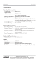
ACF-10 Series Rev. 1a, 2/03 • Specifications Operating Characteristics On Indication ................... Red LED (4) Output Capacity: Relay Contact ............... 240 V 2 A AC 30 V 2 A DC (resistive load) Sensitivity Adjustment ..... Adjusting by offset and gain trimmers Output Functions ............. Detect switch On Delay adjusting trimmer (approx. 0.1 to 7 sec.) Off Delay adjusting trimmer (approx. 0.1 to 7 sec.) Ambient Temperature ...... -10 to 70°C (14 to 158°F) without dewing Ambient Humidity ....
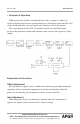
Rev. 1a, 2/03 ACF-10 Series • Principle of Operation When grains flow within a distributed tube such as a pipe or a chute, by collision and friction between grains themselves or between grains and the wall of the distributed tube, various sounds and vibrations will be generated. The sound pickup of the ACF-10 attached outside the distributed tube receives the generated sounds and vibrations and converts the signal to a relay output.
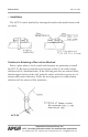
ACF-10 Series Rev. 1a, 2/03 • Installation The ACF-10 can be attached by fastening the band or the metal fixtures with two bolts. Cautions in Selecting a Place to be Attached Select a place where a lot of sounds and vibrations are generating to install the ACF-10. Be sure to install the receiving part so that it can contact firmly with the wall of a distributed tube. If the receiving part does not contact firmly due the rugged surface of the wall, paint the surface with silicon grease etc.
Rev. 1a, 2/03 ACF-10 Series • Wiring 1 2 3 4 NO Line Supply Voltage: 24-264V AC/DC Relay Contact Output: 240V 2A AC (resistive load) Automation Products Group, Inc. APG...Providing tailored solutions for measurement applications Tel: 1/888/525-7300 • Fax: 1/435/753-7490 • www.apgsensors.com • sales@apgsensors.
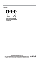
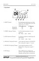
ACF-10 Series Rev. 1a, 2/03 • Adjustment 1 6 NON DETECT ZERO DETECT OFFSET 2 1. DETECT Switch Detect On Non Detect 3 RY ON GAIN 4 ON DELAY OFF DELAY 5 For shifting the magnetizing state of the output relay. The magnetizing state of the output relay is as follows: At Non-Detection At Detection OFF ON ON OFF 2. OFFSET Adjusting Trimmer An offset adjusting trimmer for noise component left ... larger right ... smaller 3.
Rev. 1a, 2/03 ACF-10 Series Preparations Attach the ACF-10 to a distributed tube to check up again the wiring before switching on. After switching on, the ACF-10 starts operating in an initial time of some 2 seconds by the initial time circuit. Within the initial delay time, the relay will not operate. (1) Flow Detection Set the OFFSET trimmer to center, the GAIN trimmer to extreme left (min.) and the DETECT switch to DETECT position before starting the following procedures.
ACF-10 Series Rev. 1a, 2/03 Other Functions (1) Setting of DETECT switch • Depending upon position of DETECT switch, the relay will operate as follows: Relay OFF ON Contact OPEN CLOSE Relay Detect Side ON Non Detect Side OFF Contact CLOSE OPEN Detect Side Non Detect Side (2) Setting of DELAY TIME ON DELAY 0.1 to 7 seconds OFF DELAY 0.1 to 7 seconds ON DELAY: Delay in output for change from non-detection to detection. OFF DELAY: Delay in output for change from detection to non-detection.
Rev. 1a, 2/03 ACF-10 Series • Cautions on Handling Wiring Use the connection cables of ø5 to ø10 mm cross section. If using cables other than specified diameter and strained cables, drip-proof must be maintained. Treat the cable as shown in the following figure. After passing the cable through the cable gland, making press-fit is recommended for easy-to-work. Shape of solderless terminals for cable Use the solderless terminal with the size as shown in the figure below.
ACF-10 Series Rev. 1a, 2/03 Other Cautions • If the ACF-10 is dropped or receive a strong shock, it may be damaged. Handle with care. • Do not use the ACF-10 in a vapor and corrosive gases or misty environments. • Be sure to check up the terminal numbers before wiring. Be sure to fasten the cable gland and the cover. If the fastening is loose, this may damage the drip-proof.
Rev. 1a, 2/03 ACF-10 Series • Dimensions — in./mm 1.97 50 3.15 80 4.21 107 0.02 0.5 1.65 42 Automation Products Group, Inc. APG...Providing tailored solutions for measurement applications Tel: 1/888/525-7300 • Fax: 1/435/753-7490 • www.apgsensors.com • sales@apgsensors.
AUTOMATION P R O D U C T S G R O U P, I N C. APG...Providing tailored solutions for measurement applications Automation Products Group, Inc. Tel: 1/888/525-7300 1/435/753-7300 Fax: 1/435/753-7490 e-mail: sales@apgsensors.com www.apgsensors.com Automation Products Group, Inc. 1025 W. 1700 N.