APOLLO Gate Operators, Inc.
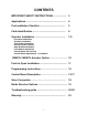
CONTENTS IMPORTANT SAFETY INSTRUCTIONS ..................... 3 Applications .............................................................. 4 Pre-Installation Checklist ........................................ 5 Parts Identification ................................................... 6 Operator Installation ................................................
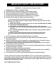
IMPORTANT SAFETY INSTRUCTIONS WARNING - To reduce the risk of injury or death: • • • • • • READ AND FOLLOW ALL INSTRUCTIONS. Installation should be performed by a professional installer. Required welding should be performed by a qualified welder. Should electricity be required, use a certified electrician only. Any device that requires 120 Volts AC should be U.L. approved. Review with the owner all safety concerns including: ⇒ Do not operate the gate unless area around gate is in full view.
APPLICATIONS The Apollo Model 1550ETL/1650ETL Swing Gate Operator is approved for Vehicular Class I & II usage under UL 325 Guidelines, and is designed to handle swing gates up to 16 feet in length and 600 pounds each. A professional fence or gate dealer is recommended to assure proper installation. Apollo Gate Operators are available only through qualified dealers with an outstanding reputation in the fence and gate industry.
PRE-INSTALLATION CHECKLIST The following check list should be used before beginning installation: Verify that the proper operator has been selected for this application. Verify proper installation and operation of the gate. 1. Are the hinges servicable? 2. Does the gate swing free and level? 3. Will the gate require a locking device? 4. Is the hinge and stop posts sturdy enough to handle the gate & operator? 5. Does the gate meet U.L.
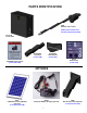
PARTS IDENTIFICATION 816E Actuator with 8’ cable (816EX slave actuator with 38’ cable supplied with 1650) #11111B Control Box #10000415 Pivot Arm (2 with 1650) #10025215 Gate Bracket (2 with 1650) #1125 Hardware Kit (2 with 1650) #273G CAUTION Signs (2 each) (4 each with 1650) OPTIONS #201 5 Watt Solar Panel & Bracket (optional) (2 required with 1650) #404C Automatic Battery Charger (optional) 6 #446 Bolt On Pivot Arm (optional) (2 required with 1650)
OPERATOR INSTALLATION STEP 1 PIVOT ARM INSTALLATION (standard pull to open) Location of Pivot Point. Notes: PULL TO OPEN pulls gate open (actuator is extended when gate is in the closed position). PUSH TO OPEN pushes the gate open (actuator is retracted when gate is in the closed position). For PUSH TO OPEN installations see page 12. If a 400 Upgrade Kit is to be used, refer to the 400 instructions for pivot point location. The following instructions provide up to 105o of swing.
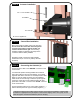
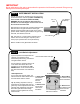
STEP 2 Actuator Installation 1/2” x 3 1/2” Hex Bolt 1/2” Washer 1/2” Lock Nut Do not over tighten nut STEP 3 Control Box Installation Mount the control box within 4 feet of the pivot arm. Do not mount the control box where the person using the push button on side of the box can come in contact with the gate. Use mounting hardware capable of supporting the weight of the control box with the battery installed.
IMPORTANT Never weld parts to the gate or posts when the operator circuit board is powered. Doing so may damage the board beyond repair. STEP 5 GATE BRACKET INSTALLATION Activate push button on the side of the control box and extend the actuator until it stops (PULL TO OPEN only, leave actuator retracted for PUSH TO OPEN). WARNING: Do not let extension tube rotate as it extends.
1550ETL / 1650ETL Actuator Option The Apollo 1550ETL and 1650ETL systems – which use the 835/836 boards – come standard with the 816E / 816EX actuators. These actuators have a gray cable restraint and are considered our “smart” or “intelligent” actuator. These actuators utilize all of the features of the 835/836 board. Please note that if a 416 (non-intelligent actuator) is to be used on a 1550ETL / 1650ETL system: 1. Switch #10 (SMART ACT.) must be in the OFF position. 2.
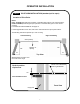
PUSH TO OPEN INSTALLATION STEP 1 PIVOT ARM (s) INSTALLATION Location of pivot point Direction of opening Hinge post Gate (closed) 6” Both measurements are taken from the center of the hinge. Top View 11” Center Line of attachment point for gate bracket Vertical position of pivot arm (s) 1/2” Pivot arm must be level Front View Hinge post Rewiring actuator (s) for push to open Must be re-wired for proper operation Strip back 6” of black sleeve from connector end of the actuator cable.
PROGRAMMING INSTRUCTIONS The 835/836 circuit boards incorporate a safety feature that will put the operator into a hard shutdown mode if the circuit board detects a current sense two consecutive times during a cycle. This hard shutdown condition can only be reset by shorting the FIREBOX or UL connectors on the left side of the circuit board to ground. If a firebox is used in the installation, The firebox door should be opened and closed to reset the circuit board.
835/836 Control Board Parts Identification Program Switches Timer To Close Dual Gate Delay Current Sensitivity Adjustments Microprocessor GateLink Connector Hard Shutdown Reset Operate Push Button Remote Monitor Outputs Optional Device Inputs LED Enable & Learn Mode Push Button Stop Circuit Jumper Control Board Reset Fire & ETL Inputs Optional Device Input Emergency Bypass Actuator Connector (Slave) Reverse Battery Polarity Indicators 13 Actuator Connector (Master)
Actuator Connector 7 5 8 3 6 1 4 2 Board Actuator Cable Function Pin 1 Pin 2 Pin 3 Pin 4 Pin 5 Pin 6 Pin 7 Pin 8 Open Limit Close Limit Motor (positive on open, negative on close) Motor (negative on open, positive on close) Common for both limit switches Feedback from intelligent actuator (816E/816EX) Battery Negative Battery Positive Orange White Black Red Green Yellow Black Red EMERGENCY BYPASS (open only) Applies battery voltage directly to motor to open gate if control board fails.
Adjustments TIMER TO CLOSE Adjusts time before gate automatically closes Adjustable 5 to 70 seconds. DUAL GATE DELAY Adjusts delay between master and slave operation 0-4 seconds (836 only for use with magnetic, solenoid, and other locking de vices) CURRENT SENSITIVITY Increases or decreases the Auto Reverse sensitivity. Push Buttons OPERATE When depressed, activates the gate. Used for initial installation and testing.
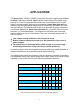
Program Switches OFF ON 1 TIMER TO CLOSE Gate does not automatically close. Gate automatically closes. 2 TIMER TO CLOSE OPT. Gate automatically closes from any position after opening. Gate automatically closes only when completely open (open limit engaged). 3 SLAVE DISABLE Enables slave side (dual gate use). Disables slave side. (single gate use) 4 SIREN DELAY Siren (optional) active when gate is moving. Siren (optional) starts 5 seconds before gate moves.
Optional Device Inputs GND Supplied Battery Ground INP Activate Gate (Push button activation when momentarily shorted to ground) 12V Supplied Battery Voltage (Protected with 3 Amp fuse) GND Supplied Battery Ground INP Activate Gate (Push button activation when momentarily shorted to ground) 12V Supplied Battery Voltage (Protected with 3 Amp fuse) EDGE Reverse edge input. When grounded, will stop and reverse gate if closing, resets close timer if gate is open. EDGE Reverse edge input.
APOLLO Gate Operators, Inc. 911 Siren The 911 Siren is included with all Apollo ETL Gate Operators. Mount siren in an area that will produce maximum performance (additional wire may be required). Connect the red wire to the SIREN connector on the Remote Monitor Output Connector block. Connect the black wire to the GND connector on the Remote Monitor Output Connector block. Red Black Set Program Switch # 4 as preferred: ON - Upon activation, Siren will start for 5 seconds before gate(s) begin moving.
APOLLO Gate Operators RECEIVER OPTIONS Do not confuse the receiver code switches with the red program switches on the gate control board. Never set all code switches to the same position. Transmitters must match code switches for proper operation.
TROUBLESHOOTING OPERATOR & ACCESSORIES Some troubleshooting will require a hand held multimeter. An inexpensive digital multimeter may be purchased at Radio Shack or a local electric supply company. Refer to the owners manual for instructions. SYMPTOM Gate opens OK but after closing, opens back up. 1. Excessive closing pressure on gate. Re-adjust the close limit switch on the actuator. 2. Automatic reverse sensitivity is set too sensitive.
SYMPTOM Gate will open using push button on side of box, but not with transmitter. 1. Code switches do not match. Check that the code switches in the transmitter and the receiver match. 2. Low or dead battery in transmitter. Replace battery. 3. Fuse blown on circuit board. Check fuses on gate control board. 4. Low battery in operator. Battery voltage should be 12 to 14 volts under load. 5. Replace receiver. Note: Code switches for receiver are inside of receiver.
SYMPTOM Gate will not open or close. Control board in HARD SHUT DOWN mode. Short the GND and UL connections on the lower left set of connectors and test. Disconnect the solar panel or charger and measure the battery voltage. Battery should read 12 or more volts and never drop below 11 volts when gate is operating. Reset program switches to factory settings. .
APOLLO Gate Operators, Inc. LIMITED TWO-YEAR WARRANTY Apollo Gate Operators are warranted against defects for a period of 24 months from the date of purchase, providing recommended installation procedures are followed.