No part of this document may be reproduced in any form or by any means without the express written consent of UPS Aviation Technologies, Inc. II Morrow, UPS Aviation Technologies, and Apollo are trademarks of UPS Aviation Technologies, Inc. © 2001 by UPS Aviation Technologies, Inc. All rights reserved. Printed in the U.S.A. UPS Aviation Technologies, Inc. Consumer Products Division 2345 Turner Road, S.E. Salem, OR 97302 U.S.A. Toll Free Canada Toll Free International FAX 800.525.6726 800.654.3415 503.391.
Welcome ... Welcome to a new era of aviation navigation. Once again, II Morrow Inc. has set new standards in features and ease of use for the general aviation public. The Apollo GX-series of products are unequaled in providing the features, level of performance, and reliability that aviation users require. The Apollo GX-series sets a precedent that will be the standard to which all other avionics will be compared.
History of Revisions Revision Date January 1998 June 1998 January 1999 March 1999 July 2001 Software Ver. 2.1 2.2 2.2 3.0 3.
Important Notice The Global Positioning System (GPS) is operated by the United States Department of Defense which is solely responsible for the accuracy, daily operation, and maintenance of the satellite constellation. System accuracy is affected by the Department of Defense’s Selective Availability (SA) and the Dilution of Precision (DOP) attributed to poor satellite geometry.
Conventions The SMALL knob is the smaller, inner knob of the two concentric rotary knobs used to look at or change information on the display. When only the SMALL knob is shown next to an example, turn the SMALL knob. The LARGE knob is the larger, outer knob of the two concentric rotary knobs used to look at or change information on the display. The LARGE knob graphic shows both of the concentric knobs. Turn the LARGE, outer knob when this graphic is shown next to an example.
Table of Contents Table of Contents Introduction . . . . . . . . . . . . . . . . . . . . . . . . . . . . . . . . . . . . . . . . . . . . . . 1-1 Apollo GX Features . . . . . . . . . . . . . . . . . . . . . . . . . . . . . . . . . 1-1 Display . . . . . . . . . . . . . . . . . . . . . . . . . . . . . . . . . . . . . . . . . . . . . . 1-2 External Annunciators . . . . . . . . . . . . . . . . . . . . . . . . . . . . . . . 1-3 Controls. . . . . . . . . . . . . . . . . . . . . . . . . . . . . . . . . . . . . . .
Table of Contents Range (Rge) . . . . . . . . . . . . . . . . . . . . . . . . . . . . . . . . . . . . . . . . 3-4 Course Deviation Indicator (CDI) and Distance Off Track. 3-5 TO/FROM Indicator . . . . . . . . . . . . . . . . . . . . . . . . . . . . . . . . 3-6 Desired Track (Dtk) . . . . . . . . . . . . . . . . . . . . . . . . . . . . . . . . . 3-6 Leg (FROM-TO) Distance . . . . . . . . . . . . . . . . . . . . . . . . . . . 3-6 Track (Trk) Angle . . . . . . . . . . . . . . . . . . . . . . . . . . . . . . .
Table of Contents Approach GPSS Operation . . . . . . . . . . . . . . . . . . . . . . . . . . 3-38 GPSS Rules . . . . . . . . . . . . . . . . . . . . . . . . . . . . . . . . . . . . . . . 3-38 Tuned Station. . . . . . . . . . . . . . . . . . . . . . . . . . . . . . . . . . . . . . . . 3-39 Tuning to a VOR. . . . . . . . . . . . . . . . . . . . . . . . . . . . . . . . . . . 3-39 Tuning to a Localizer . . . . . . . . . . . . . . . . . . . . . . . . . . . . . . . 3-40 Moving Map Functions . . . . . . . . . . .
Table of Contents Fly Direct To A US Grid . . . . . . . . . . . . . . . . . . . . . . . . . . . . 4-30 Create a User Waypoint By Basic Grid . . . . . . . . . . . . . . . . . 4-30 Fly Direct To A Basic Grid. . . . . . . . . . . . . . . . . . . . . . . . . . . 4-32 Setting Up A Search Pattern. . . . . . . . . . . . . . . . . . . . . . . . . . 4-32 Waypoint Database . . . . . . . . . . . . . . . . . . . . . . . . . . . . . . . . . . . . . . . . 5-1 Waypoint Information . . . . . . . . . . . . . . . . . . . . .
Delete Plan. . . . . . . . . . . . . . . . . . . . . . . . . . . . . . . . . . . . . . . . 6-18 Hold . . . . . . . . . . . . . . . . . . . . . . . . . . . . . . . . . . . . . . . . . . . . . 6-18 Holding Patterns (GX50/60) . . . . . . . . . . . . . . . . . . . . . . . . . 6-19 Continue. . . . . . . . . . . . . . . . . . . . . . . . . . . . . . . . . . . . . . . . . . 6-21 Load Approach (GX50/60 Only). . . . . . . . . . . . . . . . . . . . . . 6-22 Change Approach (GX50/60 Only) . . . . . . . . . . . . . . .
Table of Contents Encoding Altimeter . . . . . . . . . . . . . . . . . . . . . . . . . . . . . . . . . . . 7-20 Air Data Info. . . . . . . . . . . . . . . . . . . . . . . . . . . . . . . . . . . . . . . . . 7-21 Air Speed . . . . . . . . . . . . . . . . . . . . . . . . . . . . . . . . . . . . . . . . . 7-21 Air Temperature . . . . . . . . . . . . . . . . . . . . . . . . . . . . . . . . . . . 7-21 Altitude and Rate of Climb. . . . . . . . . . . . . . . . . . . . . . . . . . . 7-21 Heading and Turn Rate . . .
Table of Contents Manually Selecting a Flight plan Leg . . . . . . . . . . . . . . . . . . . . 9-19 Flight Plan Waypoint Sequencing . . . . . . . . . . . . . . . . . . . . . . . 9-20 Procedure Turns. . . . . . . . . . . . . . . . . . . . . . . . . . . . . . . . . . . . . . 9-21 Procedure Turn at FAF . . . . . . . . . . . . . . . . . . . . . . . . . . . . . . . . 9-22 Holding Patterns . . . . . . . . . . . . . . . . . . . . . . . . . . . . . . . . . . . . . 9-24 DME Arcs (Arc Assist). . . . . . . . . . . . .
Table of Contents User Stored Frequencies. . . . . . . . . . . . . . . . . . . . . . . . . . . . . 10-7 Weather Channels. . . . . . . . . . . . . . . . . . . . . . . . . . . . . . . . . . 10-7 Emergency Channel . . . . . . . . . . . . . . . . . . . . . . . . . . . . . . . . 10-8 Intercom Function . . . . . . . . . . . . . . . . . . . . . . . . . . . . . . . . . . . . 10-8 Stuck Mic . . . . . . . . . . . . . . . . . . . . . . . . . . . . . . . . . . . . . . . . . . .
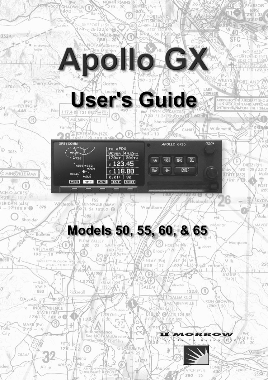
Introduction Introduction This guide describes the operation of the Apollo GX line of products. The GX50 and GX55 are GPS receivers. The GX60/65 models combine the GPS receiver with a VHF comm radio in a single package. Apollo GX Features The Apollo GX products are high performance GPS products with a high resolution moving map display configured in a 2 inch high by 6.25 inch wide standard package.
Introduction be saved with up to twenty legs for setting up custom tailored routes. The detailed Navigation information displays are also customizable and can be set to automatically scroll through the desired information. The Nearest/Emergency Search feature, invented by II Morrow (UPS Aviation Technologies), makes it easy to react to an emergency or change your active flight plan.
Introduction External Annunciators When external indicators are installed, the Apollo GX will also provide an external indication when Parallel Track (PTK) is activated or a Message (MSG) is received. The GX50/60 also have external annunciator controls for OBS/Hold and Approach Active. “Hold” refers to suspending waypoint sequencing. Controls The Apollo GX uses a variety of controls to manage the features.
Introduction Keys There are two types of keys that allow you access to the functions in your Apollo GX: permanent “hard” keys and displayed “smart” keys. Seven back lighted permanent keys are used to reach the functions or perform other operations of the Apollo GX. The “smart” key labels are shown on the bottom of the display. There are two categories of “smart” keys: those available for the Map function and those available at all other times. Press the key below the label to use the displayed function.
Introduction MAP D ENTER MAP (Graphic Moving Map) The Map key starts the Moving Map function. The entire display is used as a graphic map display. DIRECT-TO The DIRECT-TO key is used to define a direct course from your present position to a waypoint. Press once to select a waypoint. Press twice to enter an OBS desired track To or From the current active waypoint. ENTER The ENTER key enters and saves the information flashing on the display.
Introduction SYS SYS (System Mode) Press the SYS key to reach the System mode functions. System mode is used to make system level adjustments and modify Nav function displays. SKIP SKIP (Start-Up Option) Press the SKIP key during the start-up procedure to bypass the start-up tests. This is for emergencies as the IFR tests must be completed to allow IFR flight.
Introduction SCAN Waypoint SCAN Key When the SCAN key is active (highlighted) in the Moving Map display, turning the LARGE knob will move between the nearest airports. You can then press INFO to view information about that airport. In an emergency press DIRECT-TO and ENTER to fly direct to the highlighted airport. Press the SCAN key again to return the LARGE knob to normal operation. Map Setup Keys The Map Setup page displays three “smart” keys that provide a short cut for customizing your moving map.
Introduction Communicati ons Radio Mode Smart Keys (GX60/65) COM < > RCL MON MEM XIT 1-8 The Recall (RCL), Monitor (MON), Memorize (MEM), and FLIP/FLOP (<->) keys are available in the GX60/65 after the COM soft key has been pressed. COM (GX60/65) Press the COM key to operate the Communications radio functions. Flip/Flop (GX60/65) Press the FLIP/FLOP key to switch between the active (left-most) and standby (right-most) frequency while in the Com function.
Apollo GX Features Apollo GX Features Navigation Features 30 Reversible Flight Plans of up to 20 Legs with Automatic Sequencing 500 User-Defined Waypoints Nav Displays Lat/Lon Bearing and Distance Ground Speed and Track Angle Desired Track and Distance Internal CDI Display 160 pixel wide by 80 pixel high electroluminescent display with moving map Automatic Display Intensity Control User-Selectable Nav Displays User-Definable Distance and Speed Settings: nm and km (distance) knots Clock and Countdown Timer
Apollo GX Features Electrical Input voltage 10 VDC to 40 VDC, reverse polarity protected Input current (GPS navigation input) 500 mA typical, 750 mA max at 13.75 VDC 250 mA typical, 375 mA max at 27.5 VDC Input current (comm input - GX60/65 only) 270 mA typical, 2A max at 13.75 VDC, receive 130 mA typical, 900 mA max at 27.5 VDC, receive 2.1A typical, 3.2A max at 13.75, transmit 1.0A typical, 1.4A max at 27.
Apollo GX Features Serial Interface 2 RS-232 for GX50/60/65 1 RS-232 for GX55 Physical Specifications Height: 2.0 inches (5.08 cm) Width: 6.25 inches (15.88 cm) Depth: 11.125 inches (28.26 cm) behind panel, including mounting frame and connectors Weight (with mounting frame): GX50 and GX55 - 2.6 pounds (1.179 kg) GX60/65 - 3.1 pounds (1.
Apollo GX Features VHF Comm Receiver Performance Specifications (GX60/65) Class D Frequency range - 118.000 to 136.
Getting Started Getting Started This section explains how to get started using your Apollo GX. Information in this section explains how to: · Select a waypoint · Store waypoints · Find a Nearest Waypoint · Fly Direct-To a waypoint · Create a flight plan · Activate a flight plan · Use the Moving Map It is necessary to enter a seed position and the current time the first time you turn the unit on. This should have been done when your unit was installed.
Getting Started 2. The Waypoint Type will flash. Turn the SMALL knob to choose the Waypoint Type (Airport, VOR, NDB, INT, or USER). AIRPORT HIO PORTLAND city OR USA 3. Turn the LARGE knob to move the cursor (flashing character) to either the identifier or the city/facility name. Turn the SMALL knob to change the flashing character and show waypoints starting with that character. AIRPORT HIO PORTLAND city OR USA 4.
Getting Started 3. In this case we’ll keep the “A” as the second character. Turn the LARGE knob to the third character and then turn the SMALL knob to select an “L.” AIRPORT 09C KALAMAZOO city dup MI USA SEL 4. Now, press the SEL key. Note that the entire name “KALAMAZOO” flashes. AIRPORT 09C KALAMAZOO city dup MI USA 5. Turning the SMALL knob will allow you to choose from all of the waypoints that start with “KAL.” Turn the SMALL knob both cw and ccw to check the waypoints.
Getting Started Duplicate Identifier, City, or Facility Names While performing Waypoint Identifier selection, you may see the word “dup” on the bottom line. This means that there is more than one waypoint for the displayed city or facility name. The same technique described above can be used to search for duplicate city and facility names. 1. While viewing the waypoint database page, turn the LARGE knob to the identifier or facility name field. SEL 2. Press SEL to activate the whole field.
Getting Started Storing a Waypoint DB ENTER ENTER Your Apollo GX can store up to 500 user-defined waypoints in the USER database. The waypoint can be created by providing a Lat/Lon position or by a Radial and Distance from a reference waypoint. Then, you can give your waypoint a name and even include a runway length. You can use up to six characters with upper case letters, numbers, or a space for the name. You can also enter a runway length from 0 to 9999 ft.
Getting Started Finding a Nearest Waypoint NRST When you press the NRST key, your Apollo GX will search for the nearest 20 waypoints within 600 nm for each waypoint type. You can also be selective about the runway length, lighting, and surface type. See Setting Runway Limits on page 12. 1. Press the NRST key. The Nearest Waypoint function is displayed with the distance and bearing from your present position to the indicated waypoint. Near 1 to PPos SLE AIRPORT Brg 352°½ 5.4nm 2.
Getting Started Flying Direct-To a Waypoint D Pressing DIRECT-TO allows you to quickly make changes to your TO waypoint. When you press DIRECT-TO, the default waypoint shown will be the current TO waypoint in the Nav or Flight Plan functions or the waypoint displayed in the Database or Info functions. See page 31 for more details. 1. Press the DIRECT-TO key. The display will go directly into the Waypoint Database and the waypoint type will flash. VOR SALEM CITY CVO OR USA 2.
Getting Started Create a Flight Plan FPL SEL You can create up to 30 flight plans with up to 20 legs each. A flight plan name can have up to eight characters using upper case letters, numbers, or a space. 1. Press FPL. Turn the LARGE knob to reach the Create a New Flight Plan page. Then, press SEL. Press SEL to Create a New Flight Plan 2. The Plan Name page will appear and the first space will flash. The underlined spaces will disappear after you name the flight plan.
Getting Started SEL 5. The first flight plan leg page will be displayed. Press SEL to start inserting waypoints. ______ to ______ 1 Press SEL to Edit Leg ENTER 6. The Ins? prompt will flash. Press ENTER. This will take you to the waypoint database. Use the LARGE and SMALL knobs as described in the Select Waypoint section starting on page 1. Press ENTER after selecting a waypoint. Ins? to ______ 1 ___° __._nm ___ ____ SEL 7.
Getting Started Using the Moving Map MAP The Moving Map gives you a graphic presentation of your flight progress. You can select the type of waypoint displayed, a route line, ATC ring, airspace setup, type of airspace displayed, and map orientation. See the Moving Map section on page 1 for more details. Viewing the Moving Map 1. Press MAP. Turn the LARGE knob to view the map and nav information, full screen map, and map setup displays. 2. While viewing the map, turn the SMALL knob to change the map scale.
Direct-To (D ) present position to a selected waypoint. Tuned Station * * when configured Select (SEL) SUA Runway Limits Search Around WPT User WPT LocDME INT NDB VOR Airport (ARPT) Press NRST WPT Comment Sunrise/Sunset Lat/Lon Approaches Frequencies Map Bearing & Dist Radial & Dist Ident, Type, & Name Press INFO Waypoint Information (INFO) Press the indicated button and then turn the LARGE Press SEL to edit information or to select options. knob to view the pages shown.
Old Msg 1 . . .
Navigation Basics Navigation Basics This section explores the navigation function and describes the powerful features it contains. About the Navigation Function The navigation function is always active. When you use other functions, the navigation function continues to run “in the background” calculating your present position, navigating your programmed route (if active), and alerting you to events or conditions important to navigation.
Navigation Basics North TAE = Difference between Track and Desired Track TO WPT Bearing = Direction to waypoint Course = Desired Track between specific waypoints TRK rse Cou BRG Desired Track = Course direction DTK Track = Direction the aircraft is going DTK Track Angle Error (Tae) Heading = Direction the aircraft is pointed Distance Off Track or Cross Track Deviation FROM WPT Heading Present Position Navigation Terms and Abbreviations Autonav ENTER The Autonav feature lets you select ce
Navigation Basics Relative Bearing Indicator The Relative Bearing Indicator is an arrow next to the Bearing value that indicates an approximate bearing to a waypoint or airspace relative to the aircraft’s current track when your current ground speed is more than 5 knots. The following illustration describes the bearing range for each arrow.
Navigation Basics Estimated Time En Route (Ete) ETE is to the current TO (destination) waypoint from your present position based on the current ground speed. The units shown are in hours and minutes, 00:00 to 99:59, and in seconds when less than one hour is displayed. If the ground speed is less than or equal to 5 knots, the GPS receiver does not have a valid position, or there is no TO waypoint, the ETE value will be shown as dashes.
Navigation Basics Course Deviation Indicator (CDI) and Distance Off Track The triangle symbol (“) referenced to a bar graph shows your position relative to being on-course. When the bar graph is to the right of the triangle, you must fly right to return on-course. In the example below, the bar graph indicates you are off-course to the right. Fly the aircraft in the direction of the bar graph (left) to return on-course. ete aSLE #### “ Brg 173¯ CDI Sensitivity = 0.3 nm each 7 = 0.01 nm each 6 = 0.
Navigation Basics If the GPS sensor is not sending a valid position, or the current TO waypoint is blank, the CDI will display “—Nav Flagged—”. TO/FROM Indicator The triangle symbol is also used as a TO-FROM indicator. When the triangle is facing up, you are on the “TO” side of the destination waypoint. When the triangle is facing upside down, you are on the “FROM” side of the destination waypoint.
Navigation Basics resolution, 100.0 to 999.9 km at 0.1 km resolution, and 1000 to 9999 km at 1 km resolution. See page 6 for details on changing units of measurement. Track (Trk) Angle Track Angle is the angle of your actual direction of travel. Track is shown as a positive value from 0 to 359 degrees in one degree increments. Track is computed using the magnetic variation at the Present Position.
Navigation Basics ete aSLE 00:37 0.006 “ Ft01:23 137kts Minimum Safe Altitude (MSA) MSA is calculated by taking the Maximum Elevation Figure (MEF) from the sectional chart grid that corresponds to your current position. In areas below 3,000 feet, 1,000 feet is added. In areas above 3,000 feet, 2,000 feet is added. In the example below, the current aircraft would be considered to be at 7,000 feet. If you are within 5 nm of another grid with a higher MEF, the higher MEF will be used.
Navigation Basics database coverage area. In the example shown above, the MESA for the present position of the aircraft would be 16,800 ft. The mountainous terrain would add a 2,000 ft. buffer to the 14,800 ft. Maximum Elevation figure indicated from the sectional chart. Flight Time Flight Time shows the elapsed time in hours and minutes (00:00 to 99:59) from departure. If the Flight Timer is not started the value will be replaced with dashes.
Navigation Basics airport types you select, such as: runway length, lighting, and surface type. Press INFO while viewing a Nearest waypoint for more information about that waypoint. NRST Starting Nearest Waypoint & Airspace Search 1. Press the NRST key. Turn the LARGE knob to display the waypoint type or options: Airport, VOR, NDB, Intersection (INT), User (USER), Choose Reference Waypoint, Runway Limits, and Special Use Airspace. Near 1 to PPos SLE AIRPORT Brg 352°½ 2.4nm D ENTER 2.
Navigation Basics 2. The waypoint type will flash. Turn the SMALL knob to choose Airport, VOR, NDB, Intersection (INT) or User waypoint type. VOR PDX PORTLAND facil OR USA 3. Turn the LARGE knob to the waypoint identifier name. The first character of the identifier will flash. Turn the SMALL knob to change characters. Turn the LARGE knob to select the next character to change. AIRPORT SALEM city ENTER SLE OR USA 4. Press ENTER.
Navigation Basics Setting Runway Limits for Nearest Waypoints Narrow the type of airports that you will accept by choosing the runway length, lighting, and surface type. The Runway Limits selection also controls the airports that are displayed in the Map function. 1. While in the Nearest Waypoint Search function, turn the LARGE knob to view the “Runway Limits” display. Runway Limits HARD/SOFT/WATER Ft:0 Lit:No SEL 2. Press SEL. The runway length value will flash.
Navigation Basics 4. Turn the LARGE knob to cause the runway surface type to flash. Turn the SMALL knob to choose from the Hard, Soft, or Water surface types. Soft refers to grass, dirt, or gravel runways. Choices include: Hard, Hard/Soft, and Hard/Soft/Water. Runway Limits HARD/SOFT Ft:3500 Lit:Yes ENTER Controlled Special Use Airspace 5. Press ENTER to save your choices or press SEL again to disable selection and to ignore any changes you have selected.
Navigation Basics INFO 1. Press the INFO key to view information about the airspace. Values for ceiling and floor may be any number of positive feet less than 100,000. Values may also be Unlimited, Ground, FL (Flight Level, followed by a number such as 050), Unknown, or NOTAM. KANSAS CITY Ceil: 8000’msl Floor: GROUND 2. Turn the SMALL knob to view more information about the airspace. The Nearest Airspace list is updated periodically as your aircraft moves and the following display may appear.
Navigation Basics In the Nav function, turn the LARGE knob to view the Altitude Assist page. The diamond in the corner notes that turning the SMALL knob will show the Encoder Altitude, Auto Descent, End Altitude, and Hold Altitude, and Buffer values. Altitude Assist Local Altimeter Setting 29.92" · SEL Setting the Local Altimeter Value 1. While viewing the Altitude Assist page, press SEL. The setting value will flash. The default barometric pressure setting is 29.92".
Navigation Basics Setting Hold Altitude and Buffer The Hold Altitude is an altitude where you want to remain. The Buffer is the tolerance or range in altitude that you can move in vertically before a warning message is generated. Hold Altitude Flight Path Buffer 1. In the Nav function, turn the LARGE knob to the Hold Alt/Buffer page. Press SEL. The Hold Altitude value will flash. SEL Hold Alt 5650ft Buffer 150 ft ENT to Hold Alt 2. Turn the SMALL knob to change the value. 3.
Navigation Basics Auto Descent The Auto Descent feature allows you to input a desired End Altitude, an Offset Distance from a desired Auto Descent Waypoint from the Active flight plan, a desired Feet per Minute Descent rate, and an expected Ground speed.
Navigation Basics Set up your Auto-Descent by selecting: · SEL Distance from destination waypoint (0 - 99 nm) or Offset Distance · Ending altitude (-1,500 - 50,000’ in 50’ steps) · Descent rate (100 - 5,000’/min in 10’/min steps) · Estimated ground speed (50 - 600 kts) 1. While viewing either the Auto-Descent or End Alt page in the Altitude Assist function, press SEL. The Offset Distance value will flash. Turn the SMALL knob to change the Descent Offset Distance value.
Navigation Basics Parallel Track This function allows you to create a parallel course Offset offset to the left or right from your current flight plan from 0.1 to 20.0 nm. You must have FROM and TO waypoints defined. Parallel Track cannot be activated if you set a course using Direct-To. Transitions between future flight plan legs cannot have turns greater than 120 degrees.
Navigation Basics 1. In the Nav function, turn the LARGE knob to display Parallel Track. Parallel Track Offset: Standby RIGHT 12.4nm SEL ENTER 2. Press SEL. The Offset field will flash. Two states are available: Use or Standby. If Parallel Track is in use, “Standby” will flash. If Parallel Track is on Standby, “Use?” will flash. If the direction and distance values are what you want, press ENTER.
Navigation Basics ENTER MSG 5. Turn the LARGE knob back to the “Offset” field. Press ENTER when the “Use?” prompt flashes to activate Parallel Track. A “p” will appear next to the waypoint identifier to indicate that Parallel Track is in use. The MSG annunciator will flash and a message will state that Parallel Track is in use. Press MSG to view the message. Parallel Track Offset: Use? LEFT 5.0nm ete pCVO 00:22 0.034 “ Brg 186 46.
Navigation Basics Countdown Timer The Countdown Timer allows you to set a timer that will alert you when it expires with a flashing MSG annunciator. The maximum time is 99:59:59 (hours, minutes, seconds). The default time on power up is the previous time that was entered. The factory default time is 00:03:00 (3 minutes). You can stop the timer by pressing SEL twice while viewing the Countdown Timer page. 1. While in the Navigation function, turn the LARGE knob to view the Countdown Timer page. SEL 2.
Navigation Basics Arc Assist The Arc Assist function will help you to navigate along an arc. In the GX50/60, Arc Assist will help you fly approaches with DME Arcs. Arc Assist can be used as a user-defined arc to avoid special use airspaces, or for conducting aerial searches using increasingly larger circles. The Arc Assist page shows the direction of the arc (left or right), the reference waypoint identifier, the desired track for the arc, and the distance to the reference waypoint.
Navigation Basics SEL 2. Press SEL. Choose another waypoint using the LARGE and SMALL knobs. VOR CVO CORVALLIS facil OR USA 3. Select the Arc direction with the SMALL knob. Left Arc dtk 171 ref: CVO vor Rad 005° 14.0nm· Rght Arc dtk 351 ref: CVO vor Rad 005° 14.0nm ENTER 4. Press ENTER to accept the selections and start navigating. Note The DTK on the Arc Assist page is the no-wind heading to hold the distance shown. It is a tangent to the current radial.
Navigation Basics Waypoint This page shows the cumulative distance from your Distance Page current position to each waypoint in the active flight plan starting with the active leg. Turn the SMALL knob to view the next set of waypoints in your active flight plan. The waypoint type is shown to the left of the identifier. The allowable waypoint types are: Airport (a), Intersection (i), NDB (n), and VOR (v).
Navigation Basics From/To/Next The FROM/TO/NEXT Waypoint allows you to Waypoint view and/or edit a three waypoint mini-flight plan, or view two legs of your flight plan, while within the Nav function. These waypoints are like a three waypoint window into your Active Flight Plan. Changes to the FROM/TO/NEXT page change the Active Flight Plan, and vice versa. You may also Hold (sequencing suspended) or enable the TO waypoint.
Navigation Basics SEL 2. Press SEL to start editing. Turn the LARGE knob to select the FROM (first) waypoint position. Turn the SMALL knob, if necessary, so the flashing selection shows “Ins?” (Insert). Press ENTER. ENTER From Ins? To ______ Next ______ 3. The Waypoint Type will flash. Choose the Waypoint Type with the SMALL knob. AIRPORT AAF APALACHIOCOLA city FL USA 4. Turn the LARGE knob to the first character of the waypoint name. The first character of the waypoint name will flash.
Navigation Basics 6. Turn the LARGE knob clockwise one click to move to the next character. Turn the SMALL knob to select the desired character. Continue to select the needed characters. AIRPORT EUGENE city ENTER EUG OR USA 7. Press ENTER when you have selected the desired waypoint. From EUG arpt To ______ Next ______ B - Set the TO Waypoint SEL ENTER ENTER 1. Press SEL and move to the TO waypoint with the LARGE knob. The insert (Ins?) choice will flash.
Navigation Basics C - Set the NEXT Waypoint SEL ENTER 1. Press SEL and move to the NEXT waypoint with the LARGE knob. The insert (Ins?) choice will flash. Press ENTER and then select the NEXT waypoint as you did for the FROM and TO waypoints. From EUG To SLE Next Ins? ENTER arpt 2. After selecting a NEXT waypoint, press ENTER. From EUG To SLE Next HIO arpt arpt arpt D - Editing FROM/TO/NEXT Waypoints 1. While in the Navigation function, turn the LARGE knob to view the FROM/TO/NEXT page.
Navigation Basics ENTER SEL 3. Turn the SMALL knob to choose the type of editing you want to do. The flashing selection will ask you to choose between Ins (Insert), Chg (Change), or Del (Delete). The TO waypoint can also be placed on Hold. Press ENTER when you have selected the editing option. When a waypoint is deleted, its position will be replaced by dashes. The Chg and Ins choices will allow you to select a new waypoint as used in the previous examples. Placing the TO Waypoint on Hold 1.
Navigation Basics Using Direct-To Pressing the DIRECT-TO key sets your present position as the FROM location. When using the Direct-To function, the FROM waypoint identifier is overwritten with the word “Direct.” If you remove the Direct-To position with the Del? option, the old FROM waypoint is returned to that position. If you edit the FROM position, Direct-To navigation will be replaced by the new entered waypoint.
Navigation Basics Direct-To Operation 1. Press the DIRECT-TO key. The waypoint type will flash. D AIRPORT HIO PORTLAND city OR USA 2. Select the new destination (TO) waypoint using the SMALL and LARGE knobs. AIRPORT MMV MC MINNVILLE city OR USA ENTER Direct-To Examples 3. Press ENTER. The following three examples provide some of the more common ways that you can use the powerful Direct-To function.
Navigation Basics 1. You flew to the right to avoid a storm cloud and your CDI tells you to fly left, but you still have the same TO waypoint. Press DIRECT-TO. Your current TO waypoint is displayed and the Waypoint Type will flash. D AIRPORT SALEM city SLE OR USA 2. Press ENTER. You will now fly direct from your present position to your desired TO waypoint. Your CDI will now be centered, as you are “on course.
Navigation Basics FPL 1. While on the first leg of your active flight plan, you find out that you need to make another stop on the way but you don’t want to change the rest of your plan. Press FPL. While viewing the Active flight plan, turn the SMALL knob to the first leg. SLE to HIO 1** 345° 37.8nm arpt arpt D 2. Press DIRECT-TO. Select the desired waypoint using the LARGE and SMALL knobs. AIRPORT MMV MC MINNVILLE city OR USA ENTER 3. Press ENTER.
Navigation Basics Direct-To OBS Pressing the DIRECT-TO key twice starts the OBS desired track editor. OBS Desired Track allows entry of a desired track to or from the current TO waypoint. The current desired track in the navigation pages will be replaced by the OBS Desired Track value entered. You may also select the reference waypoint from your active flight plan. Waypoint sequencing is normally set as manual. When an approach is enabled, you may select either manual or automatic.
Navigation Basics 4. Press ENTER when the choices are selected. ENTER Turn Anticipation The Apollo GX will provide information for you to smoothly transition from one flight plan leg to another. Turns are drawn on the moving map. You will receive a message about ten seconds before the turn. The message will count down to the beginning of the turn.
Navigation Basics Turn anticipation will not be available when sequencing is on Hold; for the MAP or MAHP of an approach; or for the “flyover” waypoints in an approach. Wind and Turn Anticipation The graphic Turn Anticipation curve drawn on the map display is based on your current ground speed. Once you enter the turn, the graphic curve is no longer updated. You may need to increase or decrease your standard rate turn to compensate for wind.
Navigation Basics Approach GPSS Operation When the autopilot is directed by GPSS, there are few considerations when flying an approach. · · · GPSS information will not be provided after you pass the MAP. You need to follow the directions published on the approach plate. When directed to the MAHP, use the Direct-To function. GPSS information will now once again be provided to the autopilot. Certain waypoints within an approach may be coded as “Fly-over” waypoints.
Navigation Basics Tuned Station When your Apollo GX is connected to and configured to communicate with an Apollo SL30 Nav/Comm, your Apollo GX will provide information about the VOR or Localizer tuned by the SL30. The Apollo SL30 with SW version 1.2, or later, sends the Tuned Station information once every second. Earlier versions of the SL30 only sends data when the frequency is changed.
Navigation Basics Tuning to a Localizer When the connected SL30 is tuned to a Localizer frequency, the SL30 sends the decoded Localizer identifier to the Apollo GX. The Apollo GX searches its LOC-DME database for an identifier match. If the Localizer is found to be a co-located LOC-DME, the Apollo GX will provide Distance, Speed, and Time information to the SL30 and for the Tuned Station page on the GX.
Moving Map Functions Moving Map Functions Press the MAP key to reach the Moving Map function and view the progress of your flight on a graphic display. Your present position, nearby waypoints, and special use airspaces display options are user-selectable. Three main pages are available in the Moving Map function: full screen map, split screen with map and Nav info, Search & Rescue (SAR) when selected, and map setups.
Moving Map Functions TO Waypoint Identifier Special Use Airspace Sector Special Use Airspace Outer Ring Bearing to the TO Waypoint Route Line Waypoint Location Symbol Map Scale Controls ATC Ring - approx. 5 nm Radius Waypoint Identifier Present Position Symbol Distance to the TO Waypoint The LARGE knob moves to different pages of the Map function and selects waypoints when scanning. The SMALL knob changes the map scale. Waypoint Type Keys The smart keys select the display of the waypoint types.
Moving Map Functions Waypoint Scan Key The Waypoint Scan smart key allows you to select an airport to get information about while viewing the map. SCAN 1. Press the SCAN smart key. 2. Turn the LARGE knob to highlight the desired waypoint identifier. INFO SCAN 3. Press INFO to get information about the waypoint. Press INFO to return to the map display. You may also press DIRECT-TO and then ENTER to go direct-to the highlighted airport. 4.
Moving Map Functions Distance to the TO Waypoint Special Use Airspace Route Line TO Waypoint Identifier to aPDX 44.2 123 nm Your Present Position kt Bearing to the TO Waypoint 005½ 006 brg trk 0.
Moving Map Functions 2. Turn the SMALL knob to choose On or Off. ENTER 3. Press ENTER when you made your selection, or turn the LARGE knob to the next item. Map Orient The Map Orient selection allows you to choose how the top of the map display is oriented. North Up - The display is oriented so that vertical lines on the map are aligned with magnetic north. The aircraft symbol is centered in the display and will point towards the direction you are flying.
Moving Map Functions Map Reference The Map Reference selection allows you to choose either the Destination Waypoint (Dest) or your current position with an airplane icon (Plane) as the center point of the Moving Map display. SEL REF ENTER 1. In the Map function, turn the LARGE knob to reach the Map Setup page. Press SEL. The value will flash. Turn the LARGE knob to choose Map Ref for selection. Or, press the Map Reference (REF) smart key to toggle through the choices.
Moving Map Functions Note Waypoints that are in an active flight plan will show up on the moving map even if its waypoint type is set as “Off.” 1. In the Map function, turn the LARGE knob to reach the Map Setup page. Turn the SMALL knob to the Identifier & Waypoint Type page. Press SEL to start editing the waypoint types. SEL APT:¿ID VOR:ÂID Usr:ÀID INT:+ID NDB:ÁID 2. Turn the LARGE knob to choose the waypoint type that you want to edit.
Moving Map Functions Track History Your Apollo GX can store a record of its progress in memory that will be shown on the display. The Track History is shown as a series of points on the display following the path of the plane icon. Track history may be recorded by time or by distance at a selected interval. You may also select the Strategy for storing the track history points. The Full strategy choice means that track points will be stored until memory is full. Subsequent track points will not be stored.
Moving Map Functions Trk History:Off Save By:Distance Interval:0.5 2. Turn the SMALL knob to select On or Off. 3. Turn the LARGE knob to the Save By option. Turn the SMALL knob to choose Distance or Time. 4. Turn the LARGE knob to the Interval option. Turn the SMALL knob to choose the Interval value. If you chose to Save By Distance, select a distance between 0.1 and 10.0 nm. If you chose Save By Time, select a time between 1 sec. (00:01) and 10 minutes (10:00). ENTER SEL 5.
Moving Map Functions Airspace Setup The Airspace Setup selections allows you to turn Airspace notification (Alerts) or map display of Airspaces On or Off, select the distance and time buffers for airspace alerts, turn ATC rings On or Off, and to choose the Airspace types that will be used. Airspace alerts will not be given during an approach. 1. In the Map function, turn the LARGE knob to reach the Route Line/Map Orient page. Then, turn the SMALL knob two clicks clockwise. The Airspace Setup page is shown.
Moving Map Functions Airspace Buffers Three values may be adjusted for Airspace Buffers for determining CLOSE information: distance, elevation, and time. CLOSE distance may be from 0 to 99 nm at one nm intervals. Altitude values are from 0 to 9900 feet in 100 foot intervals. Time values are from 0 to 20 minutes in one minute intervals. From the Map Setup page, turn the SMALL knob three clicks cw to reach the Airspace Buffers page. SEL 1. While viewing the Airspace Buffer page, press SEL.
Moving Map Functions ATC Ring Selection When this choice is turned ON, a 5 nm radius artificial “ATC Ring” is drawn on the Map display around airports that have a control tower. From the Map Setup page, turn the SMALL knob four clicks cw to reach the ATC Ring selection page. SEL 1. While viewing the ATC Ring page, press SEL to start selection. 5 nm ATC Rings Map : Off 2. Turn the SMALL knob to choose ON or OFF. Press ENTER after completing your selection.
Moving Map Functions The Outer selection refers to the outline of the outside ring extended from the ground on up. Selecting Outer will be useful to VFR pilots who wish to avoid all airspaces. The sector selection refers to the outside edges of the sector from the ground on up unless you have altitude input which then allows for 3-dimensional information. The Sector selection is the default setting and is most useful for IFR flight.
Moving Map Functions Search and Rescue GRD MRK PAT TO Waypoint Identifier Grid Number When activated, the Search and Rescue (SAR) feature allows a simplified, automated method of performing search patterns. The search patterns supported include parallel line, creeping line, and expanding square. A line showing the route of the pattern may also be displayed on the screen of your GX. Patterns can be based on two grid types: aeronautical sectional charts (US) and a Lat/Lon grid system (Basic).
Moving Map Functions Grid Line Display While viewing the Search and Rescue (SAR) map page, you can choose how the grid lines are displayed. Press the GRD smart key to change the Grid line view. Grid line selection options are slightly different for the two grid types, US and Basic. As you zoom out to approximately 40nm the grid lines will be removed. US Grid Type The US Grid selection is based on sectional charts as shown in the Sectional chart table.
Moving Map Functions Basic Grid Type GRD – No grid lines GRD 1 – 60 minute grid lines GRD 2 – 30 minute grid lines GRD 3 – 15 minute grid lines 124º 123º 46º a b a a c b b d c b a d 30’ a c 15’ c b d d d c 45º 30’ 15’ Search and Rescue Map Setup Page The SAR Map Setup page provides selection of SAR Map (Off/On), Grid Type (US/Basic), and the Position (area of operation). 1. From the Map Setup Page, turn the SMALL knob counterclockwise two clicks to the SAR Map Setup page.
Moving Map Functions 4. Turn the LARGE knob to Position. Turn the SMALL knob to choose the position information. If you selected the US Grid type, choose the desired sectional name with the SMALL knob or the POS smart key. See the following Sectional Aeronautical Chart Grids table for the location nearest you operation. For the Basic Grid type, select the Position quadrant (NW, SW, NE, or SE) with the SMALL knob or the POS smart key.
Moving Map Functions Set the SAR Position (Basic Grid Type) 1. If you selected the Basic Grid Type, you need to set the SAR Position. From the SAR Map Setup page turn the SMALL knob clockwise to the SAR Position page. The SAR Position page only appears when the Basic Grid Type is selected. The Position location refers to the LAT/LON of the southeast starting corner for the selected grid. 130º 120º 50º One degree grid square 40º SAR Position Reference Point (i.e.
Moving Map Functions Sectional Aeronautical Chart Grids Chart Ident Seattle Great Falls Billings Twin Cities Green Bay Lake Huron Montreal Halifax Klamath Falls Salt Lake City Cheyenne Omaha Chicago Detroit New York San Francisco Las Vegas Denver Wichita Kansas City St. Louis Cincinnati Washington Los Angeles Phoenix Albuquerque DallasFt.
Moving Map Functions Selecting A Pattern Three pattern types provide you with the ability to perform a search that best suits your needs. The three types include Parallel Line, Creeping Line, and Expanding Square. PAT ENTER 1. While viewing the SAR Map page, press the PAT (Pattern) smart key. 2. Turn the SMALL knob to select the desired pattern type. Press ENTER to choose the pattern and to start selecting the available options. Parallel Line Search Page Press ENTER ENTER ENTER PAT 4-20 3.
Moving Map Functions Parallel Line Search Pattern The Parallel Line search pattern selection allows you to create a search pattern along parallel lines based on an established grid. Start Point 1 3 4 7 8 11 12 2 5 6 9 10 13 · PAT Select grid · Set spacing · Set direction · Activate pattern 1. While viewing the SAR Map page, press the PAT smart key. 2. Turn the SMALL knob to select the Parallel Line pattern type, if necessary. Press ENTER. ENTER SEL 3.
Moving Map Functions 4. Use the LARGE and SMALL knobs to select the desired Grid. 5. Turn the LARGE knob to the Spacing option. Turn the SMALL knob to select the desired pattern spacing. You may select between 0.2 and 9.9 nm. 6. Turn the LARGE knob to the Direction of Travel option. Turn the SMALL knob to select the desired Direction of Travel. You may select N/S or E/W. ENTER ENTER PAT 4-22 7. Press ENTER when selections are complete. 8. Press ENTER to activate the search pattern.
Moving Map Functions Creeping Line Search Pattern The Creeping Line search pattern is similar to the Parallel Line Search. The starting point is any selected waypoint, rather than a designated grid based on aeronautical sectionals. The creeping line search pattern will straddle the center of your flight path.
Moving Map Functions SEL ENTER 3. Press SEL. The Starting Waypoint field will flash “INS?” (insert) or “CHG?” (change). Press ENTER to start editing the Starting Waypoint selection. Start: Ins? Spacing :1.0 Direction :000· ENTER 4. Choose a waypoint using normal selection methods. Then, press ENTER. 5. The Spacing option will flash. Turn the SMALL knob to select the desired pattern spacing. You may select between 0.2 and 9.9 nm. Start:PFC arpt Spacing :1.0 Direction :000· 6.
Moving Map Functions 9. Select the Leg Length. Press SEL to start editing the Leg Length. Turn the SMALL knob to choose the Leg Length. You may select between 1.0 and 9.9 nm. SEL Leg Length:5.0 Start:RIGHT Side 10. Turn the LARGE knob to the Start Side selection. Turn the SMALL knob to choose Left or Right. This selection sets the side for the start of the search pattern.
Moving Map Functions Expanding Square Search Pattern The Expanding Square search pattern is similar to the Creeping Line Search. Rather than parallel lines, an expanding square is radiated from the Starting Waypoint according to the spacing between lines and at an angle selected for the Direction of Travel. You may select the following options: · · · Starting Waypoint Pattern spacing (0.2 to 9.9 nm) Direction of travel in 1 degree increments Spacing Start Point PAT 1.
Moving Map Functions SEL ENTER 3. Press SEL. The Starting Waypoint field will flash “INS?” (insert) or “CHG?” (change). Press ENTER to start editing the Starting Waypoint selection. Start: Ins? Spacing :5.0 Direction :000 ENTER 4. Choose a waypoint using normal selection methods. Then, press ENTER. 5. Turn the LARGE knob to the Spacing option. Turn the SMALL knob to select the desired pattern spacing. You may select between 0.2 and 9.9 nm. Start:ONP arpt Spacing :5.0 Direction :000 6.
Moving Map Functions Mark A Position When viewing the SAR Map page you may save a User waypoint to Mark a location of interest. Pressing the MRK (Marker) smart key saves a User waypoint at the present position of the aircraft when you save the waypoint. MRK 1. While viewing the SAR Map page, press MRK. 2. The User waypoint creation page will appear with the current Lat/Lon position. The default waypoint name will be SAR000 (the first time).
Moving Map Functions Create A User Waypoint By US Grid This feature allows you to set a US Grid coordinate, such as the corner of a grid, as a User waypoint so you can fly Direct-To the starting point in a grid for flying a search pattern. You must have selected the US Grid type on the SAR Setup page to have this display available. DB ENTER 1. Press the DB smart key. Turn the LARGE knob to the “Create User Wpt By US Grid” page. Press ENTER. Create User Wpt by US GRID Press ENTER 2.
Moving Map Functions Fly Direct To A US Grid After creating a User waypoint for a US Grid, you can fly Direct-To, or set a flight plan to, the starting corner of that grid to begin a search pattern. 1. Press DIRECT-TO. Turn the SMALL knob to choose the User waypoint type, if necessary. D 2. Use the LARGE and SMALL knobs to select the desired waypoint. 3. Press ENTER. ENTER 4. Navigate to the selected grid.
Moving Map Functions If you want to fly to the Bravo-Charlie 3 corner of the 45°N and 123°W grid, you would define the corner as a USER waypoint with the name “53BC3.” The SAR position is set to 40°N and 120°W. 124º 1 123º 46º 2 a b a a c b Basic Grid User Waypoint 53BC3 b d c b a d C a c 4 3 c b d d c d 45º New SAR Position Reference Point (i.e. Lat 45 and Lon 123) The “5” comes from the 5° added to 40°N. The next number, “3”, comes from the 3° added to 120°W.
Moving Map Functions 3. Press ENTER to save the displayed Grid location as a User waypoint. 53BC3 USER 44°30.00N 122°15.00W Fly Direct To A Basic Grid After creating a User waypoint for a Basic Grid, you can fly Direct-To, or set a flight plan to, the starting corner of that grid to begin a search pattern. 1. Press DIRECT-TO. Turn the SMALL knob to choose the User waypoint type, if necessary. 2. Use the LARGE and SMALL knobs to select the desired waypoint. 3. Press ENTER. 4. Navigate to the selected grid.
Waypoint Database Waypoint Database Waypoint Information The Apollo GX provides an extensive built-in database of waypoint information to aid the navigator. Waypoints in the database are divided into 5 categories. This structure allows you to easily select a waypoint as a destination, search for waypoint information, search for nearest waypoints, or insert waypoints into a flight plan.
Waypoint Database · Sunrise/Sunset times · Waypoint comment VOR Waypoint Information · Identifier, name, state, & country · Radial and distance from the VOR · Bearing and distance from present position · Map · Operating frequency · Lat/Lon coordinates · Sunrise/Sunset time · Waypoint comment NDB Waypoint Information · Identifier, name, state, & country · Bearing and distance from present position · Map · Operating frequency · Lat/Lon coordinates · Sunrise/Sunset time · Waypoint comment LOC-DME Waypoint I
Waypoint Database · Lat/Lon coordinates · Sunrise/sunset time · Waypoint comment USER Waypoint Information · · · · · · · Getting Information About A Waypoint DB ENTER Name/Identifier (User entered) Lat/Lon coordinates (User entered) Runway Length (User entered) Bearing and distance from present position Map Sunrise/sunset time Waypoint comment You can access the Waypoint database by either looking directly or by using a feature that draws information from the database, such as using Emergency Search or
Waypoint Database 3. Turn the LARGE knob to the first character of the waypoint name. The character will flash. Turn the SMALL knob to select the desired character. AIRPORT EVERETT city PAE WA USA 4. Turn the LARGE knob clockwise one click to move to the next character. Turn the SMALL knob to select the desired character. Continue to select the needed characters. PDX AIRPORT PORTLAND city OR USA 5. You can also select the waypoint by the facility name.
Waypoint Database INFO 7. Press INFO to view information about the selected waypoint. AIRPORT TTD PORTLAND-TROUTDA city dup OR USA ENTER 9. Press ENTER or INFO to leave the function. INFO Airport Info Pages The Apollo GX database holds the most needed information about each waypoint. The Airport information is described below. Similar information is available for each waypoint type. This information is shown after selecting the waypoint and pressing INFO.
Waypoint Database Bearing & distance from present position Turn the SMALL knob to show the Bearing and Distance from your present position. An arrow shows the Relative Bearing to the waypoint from your present position. ppos to SLE Bearing 341°² Distance 121nm Airport frequencies Turn the SMALL knob to view the available frequencies for the waypoint. In the GX60/65, the center three smart keys indicate the available frequencies. Press the smart key to load the indicated frequency into the Standby position.
Waypoint Database Fuel Availability Turn the SMALL knob to view fuel availability. SLE AIRPORT Available Fuel: Avgas/Jet Map Turn the SMALL knob to view a map of the waypoint and location. If the waypoint is an airport, the runway map will be shown. You can change the map scale by pressing SEL and then turning the SMALL knob. Press SEL again to disable map scaling. Runway Diagram TO Waypoint Identifier SLE 13 183 16 Runway Numbers 34 1 MSG APT Bearing to the TO Waypoint 31 INFO VOR 12.
Waypoint Database Approach Info (GX50/60 only) Turn the SMALL knob to view information about each approach. m h fi SLE NDB 31 nSL nSL RW31 nSL Scale APPR iaf faf map mahp 4nm Lat/Lon Position Turn the SMALL knob to view the Lat/Lon position. SLE lat lon AIRPORT 44°54.57N 123°00.15W Sunrise/Sunset Time Turn the SMALL knob to view the Sunset/Sunrise time for the waypoint in UTC time. You can change the day and month to view alternate times by pressing SEL and then using the SMALL and LARGE knobs.
Waypoint Database Create User The Apollo GX allows you to create up to 500 of your Waypoint by own waypoints to the waypoint database. You can Lat/Lon create a waypoint based on a Lat/Lon or using a radial and distance from another waypoint. The starting Lat/Lon coordinates are your present position You can also add the runway length.
Waypoint Database ENTER 4. Press ENTER when you have finished entering the waypoint information. HOME USER 44°24.29N Rwlen 122°51.52W 3000’ Create User A User waypoint may also be created where its Waypoint by position is referenced by a Radial and Distance from Radial/Distance another waypoint. DB ENTER 1. Press the DB soft key. Turn the LARGE knob to view the “Create User Wpt By Rad/Dis” page, and then press ENTER. Create User Wpt by Radial/Dist Press ENT 2.
Waypoint Database SMALL knobs to choose the identifier. After the reference waypoint name is chosen, press ENTER. ENTER Ref Wpt: SLE 000.0° 000.0nm 5. The first character of the radial will flash. Now select the needed characters for the Radial and Distance. Turn the SMALL knob to change characters. Turn the LARGE knob to move to the next character. Ref Wpt: SLE 040.0° 012.0nm 6. Press ENTER when you have finished entering the waypoint information. You will be prompted to create a name for the waypoint.
Waypoint Database Update User Wpt with Present Pos DB Update the Lat/Lon coordinates of an existing User waypoint to your present position. You may also change the name and other info for the waypoint. 1. Press the DB key. 2. Turn the LARGE knob to view the “Update User Waypoint” page. Press ENTER. ENTER ENTER Update User Wpt with PPos Press ENT 3. The waypoint identifier will flash. Turn the SMALL knob to choose the User waypoint you want to change. Press ENTER.
Waypoint Database ENTER 3. Press ENTER. The waypoint identifier will flash. Turn the SMALL knob to view the User waypoints. Find Wpt to Del CABIN user Press ENT ENTER 4. When the waypoint to delete is displayed, press ENTER. Modify User Waypoint DB 1. Press the DB key. Turn the LARGE knob to view the “Modify User Wpt” page, and then press ENTER. Modify User Wpt ENTER Press ENT 2. Turn the SMALL knob to view the User waypoints. Find WPT to Mod CABIN user Press ENT ENTER 3.
Waypoint Database ENTER Creating Waypoint Comments INFO SEL 5. Turn the SMALL knob to select the desired character. Continue using the SMALL knob to change characters and the LARGE knob to move to the desired character. After the correct characters are chosen, press ENTER. You may add comments to up to 200 waypoints. The comments are added while viewing the Info for any waypoint. 1. While viewing the desired waypoint, press INFO. Turn the SMALL knob to the Waypoint Comment page and press SEL.
Waypoint Database Deleting Waypoint Comments DB You may delete any of the waypoint comments that you have created. 1. Press DB and then turn the LARGE knob to the “Delete Waypoint Comment” page. Delete Waypoint Comment: 5 used Press ENT ENTER 2. Press ENTER to view the waypoint comments. The first waypoint comment page will show the waypoint identifier, waypoint type, and a portion of the comment. The waypoint identifier will flash. CABIN USER 900FT TOWER 14NW NW OF AIRPORT ENTER 3.
Waypoint Database Update User Waypoint The Update User Waypoint function allows you to change the position of an existing User waypoint to your present position. 1. In the Database function, turn the LARGE knob to “Update User Wpt With Ppos.” Then, press ENTER. ENTER Update Usert Wpt With Ppos Press ENTER ENTER 2. A list of the User waypoints is available. The User waypoint ID will flash. Turn the SMALL knob to display the desired waypoint and then press ENTER.
Flight Plan Functions Flight Plan Functions Flight plans are specific routes between waypoints you may store in the Apollo GX memory. This information is used to calculate useful flight statistics. The Flight Plan function allows you to have up to 30 stored flight plans. Each flight plan may have up to 20 legs. The Active flight plan is always used for the current flight. Inactive flight plans may be activated in the Flight Plan function and copied to the Active flight plan.
Flight Plan Functions Flight Plan pages. The active leg is the default page you will see when pressing FPL once. FPL *Active* 259nm Dest Wpt: PDT Active · 2. Turn the SMALL knob to view the individual legs of a flight plan. Two asterisks indicate the active leg. EUG to SLE 1** 353° 48.0nm arpt arpt Active Flight Plan The first plan in the Flight Plan function is the Active plan and is noted by the name *Active* with asterisks. This name cannot be changed in the Active page.
Flight Plan Functions FPL 1. Press the FPL key. Turn the LARGE knob to view the “Create a New Flightplan” page. Press SEL to Create a New Flight Plan SEL 2. Press SEL. The first character will flash. Turn the SMALL knob to select the first flight plan name character. R_______ Enter a New Plan Name 3. Turn the LARGE knob clockwise one click to move to the next character position. Turn the SMALL knob to select the next name character. You can have up to eight characters in the flight plan name.
Flight Plan Functions SEL ENTER 7. Press SEL to insert a FROM waypoint. The Ins? prompt will flash. Press ENTER to insert a FROM waypoint. Ins? to ______ 1 ___° __._nm ____ ____ 8. Turn the SMALL knob to select the waypoint type. Turn the LARGE knob to the waypoint identifier. Turn the SMALL knob to select the first character of the waypoint identifier. AIRPORT EAGLE city EAA AK USA 9. Turn the LARGE knob clockwise one click to move to the next character position.
Flight Plan Functions 11. Repeat steps 7-10 for the remaining waypoints in your flight plan. SLE to Ins? 2 ___° __._nm ____ ____ SEL 12. Press SEL when your flight plan is complete. Turn the SMALL knob to view the legs in your flight plan. Press SEL while viewing a flight plan leg page to make changes. Press SEL and then turn the SMALL knob while viewing the flight plan name page to activate or to choose other options. See the Flight Plan Options description on page 14 .
Flight Plan Functions Flight Plan Leg Information SEL Two types of information are available within flight plan legs: waypoint and flight information. Pressing INFO will provide information about the destination waypoint. Information about the ETA, ETE, Ground Speed, and Fuel is also available for each leg by selecting which option you like to view in the leg display. 1. While viewing a flight plan leg, press SEL. The From waypoint field will flash. Chg? to SLE 1 353° 48.0nm arpt arpt 2.
Flight Plan Functions ETA Estimated Time of Arrival is for the displayed TO waypoint and requires an actual ground speed of more than 5 knots. If there is no valid ETA for the leg, dashes will replace the value. EUG to SLE 1 353° 48.0nm ETA 17:36 ETA? ETA? is the same as ETA, except the Estimated Ground Speed is used for the calculation. EUG to SLE 1 353° 48.0nm ETA? 17:27 Leg ETE The Estimated Time En Route between the displayed FROM and TO waypoints.
Flight Plan Functions no valid ETE for the leg, dashes will replace the value. EUG to SLE 1 353° 48.0nm ETE 00:27 ETE? ETE? is the same as ETE, except the Estimated Ground Speed is used for the calculation. See Estimated Ground Speed on page 16 for more details. EUG to SLE 1 353° 48.0nm Leg ETE? 00:24 Fuel To? Fuel shows the amount of fuel required to get from the FROM waypoint to the TO waypoint for an inactive plan or from the present position to the TO waypoint for the Active flight plan.
Flight Plan Functions Direct-To If the leg page displayed is the currently active leg of the Active flight plan, and a Direct-To waypoint has been entered, the From waypoint will say “Direct.” The leg just prior to the currently active leg displays the leg as if the “Direct” waypoint did not exist. After sequencing, the “Direct” disappears, and the currently active leg once again displays the waypoint identifier. See page 31 for more details on using the Direct-To function.
Flight Plan Functions Leg 3 Leg 4 SLE MMV Leg 2 WPT5 Present Position CDI WPT2 Leg 1 WPT1 (Departure WPT) Flight Plan Editing You can alter any of the information you entered into the flight plans. The editing options include: Chg?, Ins?, and Del? · · · 6-10 Chg? - An existing waypoint can be changed if at least one valid waypoint exists in the database. Ins? - A waypoint can be inserted before an existing waypoint if at least one valid waypoint exists in the database.
Flight Plan Functions Changing Existing Flight Plan Legs 1. In the Flight Plan function, turn the LARGE knob to a flight plan and then use the SMALL knob to display the leg of the plan that you want to edit. HIO to TTD 3 070° 23.0nm arpt arpt SEL 2. Press SEL. The FROM waypoint will flash with the Chg? prompt. Turn the LARGE knob to the desired waypoint. HIO to Chg? 3 070° 23.0nm arpt arpt ENTER ENTER 3. Press ENTER. This takes you into the waypoint database.
Flight Plan Functions SEL 2. Press SEL. The From waypoint will flash with the Ins? prompt. Turn the LARGE knob, if necessary, to the waypoint you want changed. HIO to Chg? 3 067° 75.0nm arpt arpt 3. If another option was last used, turn the SMALL knob to choose Ins?. HIO to Ins? 3 067° 75.0nm arpt arpt ENTER 4. Press ENTER. Use the LARGE and SMALL knobs to select the desired waypoint. AIRPORT TTD PORTLAND city OR USA ENTER 5. After selecting the waypoint name, press ENTER. HIO to TTD 3 070° 23.
Flight Plan Functions 2. Press SEL. The From waypoint will flash with the Chg? prompt. Turn the LARGE knob to the waypoint you want changed. SEL HIO to Chg? 3 070° 23.0nm arpt arpt 3. Turn the SMALL knob to choose Del?. HIO to Del? 3 070° 23.0nm arpt arpt 4. Press ENTER. The waypoint will be deleted. Each flight plan leg will shift back to replace the deleted leg, i.e. after deleting leg 3, leg 4 will then become leg 3. ENTER HIO to DLS 3 067° 75.
Flight Plan Functions Flight Plan Options In the Flight Plan function you may make changes to a flight plan. 1. In the Flight Plan function turn the LARGE knob to a flight plan name page. SEL ENTER 2. Press SEL and then turn the SMALL knob to view the available functions. 3. Press ENTER to activate the option. Activate Pressing ENTER when the “Activate” option is displayed copies the selected inactive flight plan to the active plan and activates the plan starting at Leg 1.
Flight Plan Functions Rev Activate Pressing ENTER when the “Rev Activate” option is displayed copies the selected flight plan to the active plan in reverse waypoint order and starts it at leg 1. Route 2 259nm Dest: Wpt: PDT Rev Activate? Reactivate Press ENTER when the “Reactivate” option is displayed to reset the active leg to leg 1 and allow waypoint sequencing. Only used for the Active plan.
Flight Plan Functions Copy Plan Pressing ENTER when the “Copy Plan” option is displayed allows you to copy any existing plan into the current plan, overwriting all of the current plan’s waypoints. You may choose the active or any inactive flight plan. SEL ENTER 1. While viewing the desired flight plan, press SEL and then turn the SMALL knob to the “Copy Plan?” option. Press ENTER. Route 2 259nm Dest: Wpt: PDT Copy Plan? 2.
Flight Plan Functions Clear Waypoints Pressing ENTER will delete all waypoints in the selected flight plan. The plan name will remain. Route 2 259nm Dest: Wpt: PDT Clear Wpts? Reverse Flight Plan Pressing ENTER when the “Reverse” option is displayed reverses all the waypoints in the current flight plan. This option is available only on inactive flight plans with two or more waypoints.
Flight Plan Functions plan or “Fuel To Uses Est Gr Speed” when the current flight plan is an inactive, stored flight plan. Delete Plan Pressing ENTER when the “Delete Plan” option is displayed deletes the current flight plan. The display returns to the previous flight plan’s name (or first) page. The *Active* flight plan cannot be deleted, in which case this option is not displayed.
Flight Plan Functions ENTER 3. Press ENTER to place the active flight plan on hold. Waypoint sequencing will be inhibited on the current leg. Pressing OBS/HLD will also work. *Active* 259nm Dest: Wpt: PDT Holding Holding Patterns (GX50/60) A holding pattern is operationally the same as a procedure turn except that you usually intend to make repeated crossings of the waypoint on a specific inbound course. For a holding pattern, like for the procedure turn, the steps will always be to: 1.
Flight Plan Functions selected inbound course and through the waypoint. The CDI will indicate “fly-left” if the aircraft is to the right of the desired track with reference to the selected inbound course. The CDI will indicate “fly-right” if the aircraft is to the left of the desired track with reference to the selected inbound course. As with traditional VOR navigation, these indications are always related to the aircraft position and not to the heading or direction of flight.
Flight Plan Functions with 020° inbound selected as the “OBS” course to UBG. "TO" Side "FROM" Side HIO (NEXT) UBG (TO) 0 02 r ula dic pen Per If sequencing is enabled on the "TO" side of a line perpendicular to the destination waypoint, the flightplan will sequence to the "NEXT" waypoint when you cross the line. If sequencing is enabled on the "FROM" side of a line perpendicular to the inbound course at the active destination waypoint, the flightplan will sequence immediately to the "NEXT" waypoint.
Flight Plan Functions ENTER 3. Press ENTER to continue the active flight plan. Waypoint sequencing will be enabled. *Active* 259nm Dest: Wpt: PDT Active · Load Approach (GX50/60 Only) This option is available for the Active flight plan when a datacard with approach information is inserted into the GX50/60. Press ENTER to show the available approaches for the destination airport. Press SEL while in the Nav or Map functions to go directly to this option. *Active* 56.
Flight Plan Functions Enable Approach (GX50/60 Only) This option is available on the Flight Plan home page when an approach is already loaded, but not enabled, and you are within approximately 30 nm of the destination airport. Press ENTER to enable the approach. *Active* 56.1nm Dest Wpt: PDX Enable Approach? Disable Approach (GX50/60 Only) This option is available on the Flight Plan home page when an approach is already loaded and enabled.
Flight Plan Functions INFO 1. While viewing the desired flight plan, press INFO. Turn the SMALL knob to reach the Comment page. Waypoint Comment Press SEL SEL 3. Press SEL. Turn the SMALL knob to select the first character. _ 4. Turn the LARGE knob clockwise one click to move to the next character position. Turn the SMALL knob to select the next comment character. GOOD RESTAURANT ENTER Saving an Active Flight Plan FPL 5. After selecting the waypoint comment, press ENTER.
Flight Plan Functions SEL ENTER ENTER 2. Press SEL and then use the LARGE and SMALL knobs to enter a new plan name. After entering the name, press ENTER. PLAN 9__ Enter a New Plan Name 3. Press ENTER a second time or turn the SMALL knob twice to return to the Inactive Flight Plan name page. Don’t insert any waypoints. PLAN 9 0.0nm Dest wpt: —— Inactive · SEL ENTER 4. Press SEL and turn the SMALL knob to show the Copy Plan? option. The option will flash. Press ENTER. PLAN 9 0.
Flight Plan Functions An old navigation method 1. While holding your watch horizontal, point the hour hand at the sun. 2. Halfway between the hour hand and 12:00 is south. Don’t always depend on this method, but it is kind of fun.
System Functions System Functions Pressing the SYS key allows you to access the System functions. After pressing the SYS key, turn the LARGE knob to view the available functions: Navigation Info, System Info, Position Sensors, Misc Sensors, and Comm Info (GX60/65 only). Press ENTER when viewing the desired System function. Press Navigation Info Navigation Information SYS . Turn LARGE Knob System Info , then press GPS Sensor ENTER Misc Sensors .
System Functions SEL 1. While viewing the Autonav Time page, press SEL. Autonav Time: 4 Seconds/Page 2. Turn the SMALL knob to select the delay time. Autonav Time: 7 Seconds/Page ENTER NAV 3. Press ENTER when finished. 4. Press NAV. While viewing the Nav functions, Press ENTER to start Autonav scrolling. Press ENTER again to stop Autonav scrolling.
System Functions SEL 4. Press SEL to activate editing. The first Nav field will flash. ete SLE 00:20 2.00 “¼¼ Dtk 353 48.0nm 5. Turn the SMALL knob to select the desired Nav information to be displayed in that field. GroundSp 100 kts 2.00 “¼¼ Dtk 353 48.0nm 6. Turn the LARGE knob to move to the next field to edit. Turn the SMALL knob to select the Nav information. GroundSp 100 kts Trk 353 Dtk 353 48.0nm ENTER 7. When you are finished selecting Nav page information, press ENTER.
System Functions SEL ENTER Selecting Autonav Pages 1. While you are viewing a Nav page information page, press SEL and then ENTER. See page 5 for a listing of Nav Page choices. 2. You will be prompted to decide if you want to include this page in the Autonav scrolling. Turn the SMALL knob to choose between Yes and No. Nav Page 4 in Autonav Pages? Yes ENTER 3. Press ENTER. Restoring Default Nav Pages 1.
System Functions Nav Page Choices The following displays are available when customizing your Nav displays. Page references are shown in parentheses. Ete aUAO 02:27 Estimated Time En Route to TO 4wpt () Eta aUAO 00:02 Estimated Time of Arrival to TO wpt (9) Eta aCVO 00:22 Estimated Time of Arrival to last wpt in plan Elapsed Flight Time (9) Ft00:04 Trk 318 1.
System Functions Setting Units of Measurement Nav displays that show distance may be selected to show either nautical miles, statute miles, or kilometers. 1. In the Navigation section of the System function, turn the LARGE knob to the Nav Mode Display Pages. Nav Mode Display Programmable and Autonav Pages · 2. Turn the SMALL knob to reach a programmable Nav page. ete SLE 00:20 2.00 “¼¼ Dtk 353 48.0nm SEL 3. Press SEL to start field selection. Turn the LARGE knob to the desired field. ete SLE 00:20 2.
System Functions Magnetic Variation Automatic or Manual Magnetic Variation can be set in this page. Automatic is the default setting on power-up, unless the database is invalid. Manually set Magnetic Variation to 0° to orient your navigation to True North. 1. In the Navigation section of the System function, turn the LARGE knob to the Magnetic Variation page and then press SEL. SEL Mag Variation Auto 18°E SEL to Edit 3.
System Functions Flight Timer Trigger The following procedure is used to edit the flight timer trigger speed. The flight timer may be set to start at power-up, or when the ground speed exceeds from 10 to 500 knots. The default (factory) setting is 60 knots. The feature may also be turned off. 1. In the Navigation section of the System function, turn the LARGE knob to reach the Flight Timer Trigger page. Press SEL. SEL Flight Timer Trigger At 60 kts 2.
System Functions With the May Clear Direct-To Entry Option, the Direct-To waypoint will be inserted in the Active flight plan, and all of the other waypoints will be deleted from the Active flight plan, including approaches. With the Never Clears Direct-To option, the Direct-To waypoint is inserted before the current TO waypoint. This is the normal, default setting. Use this setting if you are using approaches.
System Functions CDI Scaling The CDI Scaling option allows you to select manual or automatic full scale deflection of the internal CDI. Manual full scale deflection options include: 0.30 nm, 1.00 nm, and 5.00 nm. Automatic scaling will use 5.00 nm as the setting. In an enabled approach operation (GX50/60), scaling is locked in automatic and will change to the appropriate scale according to your distance to the destination waypoint. SEL 1.
System Functions System Information The System Information area provides the following pages: Software and Database Version, Display test, Owner Info, and Date and Time, . Turn LARGE Knob Date & Time SW Ver & Fuel Baro Test Display Serial No. Measure Measure Display Brightness SYS ENTER Owner Name Database Default Address GPS Sensor High Phone Comm Radio (GX60/65 Only) Low Aircraft Date and Time 1. Press the SYS key.
System Functions 5. Turn the LARGE knob to move to the Month value. Turn the SMALL knob to choose the month. Date: 24 APR 97 Time: 23:24 UTC SEL to Reset 6. Turn the LARGE knob to move to the Year value. Turn the SMALL knob to choose the year. Date: 24 APR 97 Time: 23:24 UTC SEL to Reset 7. Turn the LARGE knob to move to the Time-Hours value. Turn the SMALL knob to choose the hours. Turn the LARGE knob to move to the Time-Minutes value. Turn the SMALL knob to choose the minutes.
System Functions 2. Turn the SMALL knob cw one click to view the Database Version page. Americas DB Expires mm/dd/yy Version: x.xx 3. Turn the SMALL knob cw one click to view the GPS Software Version page. GPS Sensor SW Version x.x PN:123456789 Fuel Measure Units (GX50/60 Only) The GX50/60 allows you to choose the units of measure for your fuel displays. Fuel units may be displayed as US Gallons (USG), Imperial Gallons (IMG), Liters (L), Pounds (LBS), or Kilos (KGS). 1.
System Functions Barometric Measure Units (GX50/60 Only) This function allows you to choose the units of measure for the Local Altimeter Settings. The choices are inches (“) or millibars (MB). 1. In the System Information section of the System function, turn the LARGE knob to reach the Baro Measure page. Baro Measure usg US Gallons 2. Press SEL to enable selection. Turn the SMALL knob to choose the desired units and then press ENTER.
System Functions ENTER 2. Turn the SMALL knob to choose Default, High, or Low. Press ENTER to store the desired choice. Your choice is kept until you change it. Viewing Owner Information The Owner Information function allows the user to enter their Name, Address, City, Phone, and Aircraft. As a security feature, the user must enter a password to enable editing of the Owner Information. 1. In the System function, turn the LARGE knob to reach the Owner Information page. Owner Name: WILBUR WRIGHT · 2.
System Functions Editing Owner Information It is necessary to enter a password before editing owner information. Editing is then enabled until the unit is turned off. SEL 1. Start editing by pressing SEL. User Must First Enter Password.. 2. The password entry page is then ready. Select the characters with the SMALL knob and move to the next character to the right by turning the LARGE knob cw. When you turn the LARGE knob, the last character is erased to enforce secrecy of your password.
System Functions 5. Turn the SMALL knob to go to the next Owner Information page you want to edit. Press SEL to start editing. Select the characters with the SMALL knob and move to the next character to the right by turning the LARGE knob cw. Press ENTER to save the information. GPS Sensor The GPS Sensor selection provides information about GPS satellite health, the GPS satellites available, information on each satellite, GPS Time, and GPS Reset.
System Functions 3. Turn the SMALL knob to view the GPS Satellites Used for Position fixes page. SV means space vehicle, which is the same as a GPS satellite in this case. GPS SVs for Fix 28, 31, 27, 26, 19, 07, 02, 18 4. Turn the SMALL knob again to view the GPS Satellite Status, Elevation, SNR, and Azimuth page. Continue turning the SMALL knob to view information about each available satellite.
System Functions GPS Date and Time Page In the GPS Sensor Information function, turn the SMALL knob to view the GPS Date and Time page. This page is not shown when using the Simulator. GPS Time (UTC) May 24, 1997 17:54:27 GPS Normal Reset Page Resetting the GPS receiver resends current time, date, and position to the GPS receiver. This forces a new search of the satellites.
System Functions Miscellaneou s Sensors The Miscellaneous Sensor section of the System function displays information concerning the Fuel/Air Data Sensor (F/ADS), fuel sensor, and altitude encoder when they are installed. The F/ADS includes a fuel sensor and altitude encoder. The F/ADS monitors fuel flow, air speed, outside air temperature/pressure, and magnetic heading.
System Functions Air Data Info If the Air Data Sensor is installed, the following information is available. Air Speed True Airspeed - speed of the aircraft relative to the surrounding air speed. Indicated Air Speed - Speed of the aircraft as shown on the airspeed indicator. Air data Info TruAirSp 163kts IndAirSp 149kts· Air Temperature True Air Temperature - Temperature compensated for wind chill factors. Outside Air - Temperature without compensation for wind chill. TrueAir° 10°C OutAir° 8°C Mach 0.
System Functions Wind Direction and Speed True Wind Direction, Magnetic Wind Direction, and the outside Wind Speed are displayed. Wind Dir 000°Tru Wind Dir 342°Mag Wind Spd 15kts Fuel Info An installed Fuel Data Sensor will provide the following information. Fuel Endurance · · · Estimated fuel Endurance based on the current amount of fuel in the regular (nonreserve) tanks at the current burn rates Nautical miles per fuel unit Remaining fuel (not including reserves) Endurance 20:18 nm per usg —.
System Functions Right Engine Fuel · · Burn rate for the right engine in fuel units per hour Amount of fuel used by the right engine since power up Right Engine Burn 17.7usg/hr Used 11usg Left Engine Fuel · · Burn rate for the leftt engine in fuel units per hour Amount of fuel used by the left engine since power up Left Engine Burn 16.
System Functions Fuel Measure The GX50/60 allows you to choose the units of measure for your fuel displays. Fuel units may be displayed as US Gallons (USG), Imperial Gallons (IMG), Liters (L), Pounds (LBS), or Kilos (KGS). Fuel Measure usg US Gallons SEL ENTER 7-24 Press SEL to enable selection. Turn the SMALL knob to choose the desired units and then press ENTER.
Message Function Message Function Message function is responsible for warning the user of changing conditions which require immediate attention. Press the MSG smart key to view the message. Press the MSG key again to return to the previous function. However, if a new message occurs, pressing MSG will not return to the previous function until all new messages have been viewed.
Message Function While any old message exists, the MSG annunciator remains steadily on at all times unless new messages arrive or all old message conditions go away. The home page in message mode is the first new message, if one exists, or the New Message Summary page if no new messages exist. New Messages MSG The New Message page shows how many new messages are stored. 1. Press MSG. Turn the LARGE knob to switch between New and Old Messages.
Message Function Messages The following is a summary of the conditions that cause a message warning, and examples of the messages generated for each condition. Special Use Airspace Messages Following is a list of the types of airspace messages which can be generated. All of the airspace messages become old messages after they are viewed. The Airspace Messages are unique in Message Mode in that they are the only messages which the INFO key is used to find out more information concerning the message.
Message Function CLOSE Altitude This condition occurs when the airspace boundary is within 500 feet, or a user-selected limit in the System function. Within 500’ of NORTON AFB Class C INSIDE This condition occurs when the plane penetrates the airspace. Inside of SAN DIEGO Class B Empty TO Waypoint: Cannot Compute Nav Anytime the current To waypoint is empty, this message is generated. It becomes an old message after viewing.
Message Function GPS Sensor Lat/Lon Failure When the GPS sensor cannot compute the latitude and longitude, the following message displays. It becomes an old message after viewing. GPS Position Sensor Cannot Compute Lat/Lon GPS RAIM Not Available When RAIM detection is not available for the GPS sensor, a warning is generated. The current flight phase is displayed first (Terminal, En Route, or Approach). Approach warnings are for the GX50/60 only. Messages become an old message after viewing.
Message Function GPS Communications Failure GPS HDOP Position Error When the HDOP for the GPS sensor exceeds current flight phase HDOP requirements, a warning is generated and Nav data will be flagged as invalid. The current flight phase is displayed first (either Terminal or En route). Approach warnings are for the GX50/60 only. Messages become an old message after viewing.
Message Function Set Barometer (GX50/60 Only) When an approach is enabled, you are prompted to enter the local altimeter setting. Enter Local Altimeter Setting 29.92in No Valid Altitude Input for Approach (GX50/60 Only) An approach is not valid unless an altitude value is available. Abort Approach No Valid Altitude Input Approach RAIM Unavailable (GX50/60 Only) An approach is not valid unless RAIM is available.
Message Function Altitude Range Error When the altitude encoder reports an altitude that is out of range, the following message is created. Altitude Out of Range Altitude Encoder Communications Failure This message appears when communications fail between the Apollo GX and the altitude encoder. Altitude Encoder Communications Failure Fuel/Air Data Sensor Communications Failure This message appears when communications fail between the Apollo GX and the fuel air data computer.
Message Function Outside Hold Altitude Buffer You have gone above or below the selected Hold Altitude Buffer. Altitude Alert 500ft Above Hold Altitude Start Auto Descent Begin Descent To NOONS 500ft/min 130kts Arrival At Auto Descent Altitude Arrival At 2000ft Target Descent Altitude Arrival At The TO Waypoint The arrival message is generated when you are within 36 seconds of arrival at the current TO waypoint, except when turn anticipation is active.
Message Function FROM TO TO Leg 2 WPT 3 WPT 2 Angle Bisector Leg 1 FROM WPT 1 Apollo GX with F/ADS Wind Info Arrival: SLE Next DTK 321° Desired Hdg 324° In addition to the arrival waypoint identifier, the next leg’s desired track is shown when available; otherwise, it is dashed. If wind factors (from the Fuel/Air Data Sensor) and a next waypoint are available, the desired heading is also shown on line three; otherwise, line three is blank.
Message Function Holding at the TO Waypoint This form of the Arrival Alert is provided when holding at the current TO waypoint. Arrival: SLE - Holding Next Leg is DME Arc This type of Arrival Alert is provided when the next TO waypoint is the end of a DME Arc holding at the current TO waypoint. Press ENTER to transition directly to the NAV mode DME Arc Assist page.
Message Function DME Arc Sequence (GX50/60 Only) This form of Sequence Alert is provided when the next TO waypoint is the end of a DME Arc in a nonprecision approach. Press ENTER to transition directly to the NAV mode DME Arc Assist page. Sequence Alert DME Next-Use ARC Assist? Enter Auto OBS Crossing Holding Waypoint When a waypoint on hold is crossed to the From side the first time, the following message is provided. This message is not created when you cross the MAP.
Message Function User Memory Failure This message indicates that one or more user settings were not within valid limits at power-up and needed to be reset. This message is cleared after the message is viewed. Memory Failure User Setups Have Been Reset Database Expired This message indicates that the datacard expiration date is before the current UTC date. This message is cleared after the message is viewed. America Database Expires 06/30/97 Version: x.
Message Function Low Internal Battery Voltage This message is generated when low internal battery voltage is detected. It becomes an old message after being viewed. Battery voltage is checked every 15 seconds. This battery backs up the memory for information added by the user, such as user waypoints and stored flight plans. Low Battery Voltage: Unit Needs Service High Battery Voltage This message is generated when high or zero battery voltage is detected. It becomes an old message after being viewed.
Comm Radio Operation Comm Radio Operation This section introduces the basic operating details of the VHF Communications Transceiver portion of the Apollo GX60/65. The Comm information is displayed in the bottom row of the display: Active (A) and Standby (S) frequencies. The Active (A) indicator changes to “Tx” when you are transmitting. The Standby (S) indicator changes to an “m” when the monitor function is used.
Comm Radio Operation Selecting Frequencies New frequencies are first selected as a Standby frequency and then toggled to the Active side when desired. While viewing the frequency display, use the LARGE and SMALL knobs on the right side of the GX60/65 to select the desired frequency. The Standby frequency is highlighted (reversed). 1. Press COM to reach the Comm radio function. The Smart keys will change to show the Comm functions. 2.
Comm Radio Operation Comm Mode The first page of the Map mode includes the moving Map Display map, TO waypoint, range to the TO waypoint, ground speed, bearing to the TO waypoint, track, Active and Standby frequencies, distance off-track, and the map scale. While viewing the map display, press the COM smart key to allow access to the Comm radio functions. When the Standby frequency is highlighted, use the LARGE and SMALL keys to change the Standby frequency.
Comm Radio Operation Recalling a Frequency The GX60/65 can access several areas of stored frequencies. The GX60/65 can access airport frequencies from its database of: Nearest, TO, FROM, INFO, automatically stored active, User stored, weather, and emergency frequencies. Recall Frequency to aPDX 44.2nm 170kt 005½br 006tk SLE ati 124.55· 0.01> MSG MON RCL MEM 30 <– > *Active* 44.2nm Dest Wpt: PDX Active · SLE atis 124.
Comm Radio Operation 3a. Press ENTER to move the displayed frequency into the Standby frequency position. or 3b. Press the FLIP/FLOP key to move it into the Active position. Nearest Frequencies Freq 1 Freq 15 Freq 1 Freq 15 Destination Frequencies Freq 1 Freq 15 TO or Next Frequencies Freq 1 Freq 15 FROM Frequencies Freq 1 Freq 15 INFO Frequencies Auto Stored List Freq 1 (AUTO) User Memory (USER) Weather Freq 10 Freq 1 Freq 10 Freq 1 Freq 7 Emerg.
Comm Radio Operation Nearest Frequency The frequency list for the last Nearest Airport viewed will be available in the Comm function when you press RCL. If a diamond appears on the right, turn the SMALL knob to view more frequencies. INFO Frequency You may view up to 15 frequencies for the last airport viewed using the Info function. If a diamond appears on the right, turn the SMALL knob to view more frequencies.
Comm Radio Operation NEW Freq 1 Freq 2 Freq 9 Freq 10 D OL 1. In the Comm function, press RCL and then turn the LARGE knob to display the Auto Stack List (Auto). 2. Turn the SMALL knob to view the stored frequencies. The last used frequency is shown at the top of the list. User Stored Frequencies When you press the MEM key the Standby frequency is stored in User memory. The GX60/65 stores the last ten frequencies selected by the user.
Comm Radio Operation Weather Frequencies (When available) 162.400 MHz 162.425 MHz 162.450 MHz 162.475 MHz 162.500 MHz 162.525 MHz 162.550 MHz Note You can search for the best local weather by inserting a Weather frequency into the Standby position, pressing MON, and then turning the SMALL knob to scroll through the Weather channel choices. Emergency Channel The standard emergency channel (121.50 MHz) is stored in the memory of the GX60/65. 1.
Comm Radio Operation Stuck Mic The GX60/65 helps protect you from a situation where the microphone may get stuck in the ON or Transmit position. If the microphone is keyed for longer than 35 seconds, the GX60/65 will return to the receive mode on the selected frequency. The statement “Stuc Mic” will appear on the display in Standby frequency position until the transmit key is released. In the Moving Map function, the statement will be “Stuck.
Comm Radio Operation RF Signal Strength The RF Signal Level function shows the relative signal strength of the frequency you are listening to. The range displayed is between 0 and 255. The value will constantly change while you are viewing it as signal conditions change. RF Signal Level 119.10 087 Noise Level The Noise Level function shows the relative received noise level of the frequency you are listening to. The range displayed is between 0 and 255.
Comm Radio Operation 2. Press SEL and then turn the SMALL knob to adjust the level. Press ENTER to activate the desired level. Intercom Squelch Mic 1 095 Transmit Mic Selection The Transmit Mic selection page allows to select which microphones are available for transmitting. The choices are Mic 1 and Mic 2, Mic 1, or Mic 2. 1. In the Comm Radio Information function, turn the LARGE knob to the Transmit Mic selection page. Transmit Using Mic 1 and Mic 2 2.
Comm Radio Operation Sidetone Level Adjustment The Sidetone Level Adjustment page is used to display and adjust the headphone sidetone level. This value controls the volume while you are transmitting. 1. In the Comm Radio Information function, turn the LARGE knob to view the Sidetone Level Adjustment page. Sidetone Level 000 2. Press SEL and then turn the SMALL knob to adjust the level. Press ENTER to activate the desired level.
Start Up Displays Start Up Displays The Start Up Sequence runs each time the unit is powered on. The Start Up Sequence varies between units due to installation differences. The initial start up message is displayed for about three seconds. Apollo GX By II Morrow Startup Bypass During the startup sequence, press the SKIP “smart” SKIP key to stop the initial testing. You will be able to use all functions.
Start Up Displays Owner Message If the owner name has been previously entered (in System Mode), this page with your name is displayed for three seconds. No owner info screen is displayed if the user has not entered the owner data. Property of: II Morrow Inc Memory Tests Your Apollo GX performs a number of tests at startup to ensure proper operation. Note In the event of an emergency, you may press the ENTER key to bypass the tests. IFR navigation is NOT valid if you bypass the tests.
Start Up Displays Failure to pass the software checksum test indicates that the software memory is corrupted. The GPS board will not continue operation when the following screen is displayed. Software Test Failed: Contact IIMorrow Non-Volatile RAM Tests The non-volatile RAM validation code does the following checks every time the unit is powered up. Any tests which detect a failure reset the failed values. Generally, the non-volatile RAM test pages are not displayed, since in most cases the tests pass.
Start Up Displays Miscellaneous NVRAM or EEPROM Memory Failure All other user input values which are held in non-volatile RAM are checked for validity, producing the following message if any of the values needed to be reset. The following message is then displayed until you press ENTER. Memory Test Failure Press ENTER Database Test This checksum test compares the database checksum stored on the database card with the calculated database checksum.
Start Up Displays Database Message This page shows the database name and expiration date. If the database has expired, press ENTER to continue. Americas DB Expires mm/dd/yy Version: x.xx Seed Position Each time the Apollo GX is switched on, it must locate satellites in the sky to acquire signals before determining a position fix in a complex process involving lengthy mathematical operations. Without a seed position and the current UTC time and date, this process can take 10 minutes or more to complete.
Start Up Displays press ENTER to accept the current position, though this is not required. Ppos: 2.3nm 130° To Nrst Wpt SLE Ent-OK SEL-Chnge 2. Press SEL to change the Seed Position. SEL 3. The current Reference Position will be displayed and the Chg? prompt will flash. Ppos: 44°54.46N 122°59.69W Ref Wpt: Chg? Press ENTER to change the Reference Waypoint or turn the LARGE knob to change to Lat/Lon Reference Position.
Start Up Displays SMALL knob. Turn the LARGE knob to move to each character of the waypoint name. Waypoint Type (Airport shown here) City or Facility Name Underline indicates flashing character Waypoint Indentifier AIRPORT SLE SALEM CITY City or Facility ENTER OR USA State Country 4. When you have entered the waypoint name, press ENTER. Change Lat/Lon Reference Position 1. Set the latitude and longitude coordinates near to your current position.
Start Up Displays ENTER 4. After entering the Seed Position, you will be prompted next to clear the active flight plan. Choose Yes or No with the SMALL knob. Press ENTER to continue normal operations. Clear Active Flight Plan NO? IFR Output Tests A series of tests covering connections for IFR flight are tested if your Apollo GX has been installed and configured for IFR flight. Starting IFR Output Tests After the completion of all tests the Apollo GX will start normal navigation operation.
Start Up Displays TO/FROM FLAG -ToTo/From Flag tests and display screens are provided for the To, From, and Off conditions. Nav Valid and Nav Super Flag Tests The Nav Valid and Nav Super Flag outputs are tested next. Each of the following displays is shown for three seconds, during which the external Nav Valid and Nav Super flags should be driven as indicated by the display, which is up to the user to verify.
Start Up Displays VDI tests and display screen are provided for VDI Full Up, VDI Half Up, VDI Level, VDI Full Down, and VDI Half Down. VDI Valid and VDI Super Flag Tests (GX50 and GX60/65 only) The VDI Valid and VDI Super Flag outputs are tested next. Each of the following displays is shown for three seconds, during which the external VDI Valid and VDI Super flags should be driven as indicated by the display, which is up to the user to verify.
Start Up Displays Screen Test A full visual display test on each line of the display and all of the annunciators is run next, preceded for two seconds by the following screen. Starting Display Test... The visual display incrementally lights groups of pixels on the electroluminescent display. Checking GPS The unit shows the GPS signal strength screen in the Signal GPS Sensor function.
Start Up Displays 3. Turn the SMALL knob to view the GPS Satellites Used for the Position fixes page. GPS SV’s for Fix 31, 27, 26, 19, 07, 02 4. Turn the SMALL knob again to view the GPS Satellite Status, Elevation, Signal Strength (SIG), and Azimuth page. Turn the SMALL knob to view information about each available satellite. The status will initially display as “SRCH” to indicate that it is searching for the satellite. After locking onto the satellite signal, the status will display as “DATA.
Flight Simulator Flight Simulator Your Apollo GX is provided with a Flight Simulation program that allows you to “fly” your unit by simulating the speed and altitude. This section describes the procedures used to run the Flight Simulator. You may operate the Flight Simulator in the cockpit or in your home to familiarize yourself with the operation of the Apollo GX. About the Flight Simulator The Flight Simulator is programmed into your Apollo GX at the factory.
Flight Simulator Removing and Replacing the Apollo GX The following procedure is used to remove the Apollo GX so you can operate it at a location of your choice. . While inserting or removing the GX, Do not exert excessive turning force at the end of the cam lock travel or the unit may be damaged. 1. Remove the Apollo GX from the front panel of your aircraft. Use the 3/32” hex driver included with installation kit (p/n 998-0048 ).
Flight Simulator lock is hard to turn or the unit does not seat fully, the unit is probably binding and the mounting tube should be checked. Starting the Flight Simulation NAV The following procedure is used to start the flight simulation. It is recommended that you have a data card properly inserted into the data card slot so you can use the appropriate functions. 1. Turn on the power for the power supply. Press and hold down the NAV key as you turn on the power for the Apollo GX. 2.
Flight Simulator ENTER 6. You will be prompted to use or clear the previous Flight Plan. Turn the SMALL knob to choose Yes or No. Press ENTER. If you do nothing, the Apollo GX will automatically retain the previous Flight Plan and switch to the Nav function. The Apollo GX will go to the Nav function and a simulated GPS sensor begins tracking your position from the first From waypoint in the Active flight plan.
Troubleshooting Troubleshooting Or, what to do when nothing works! This section contains information to troubleshoot your Apollo GX product when improper operation is observed. The following table lists possible problems you could encounter while operating the unit. Examine the possible causes of the problem and take the action listed to correct the trouble. If you cannot correct the problem, contact your dealer.
Troubleshooting To Ensure Trouble Free Operation Avoid high cockpit temperatures when the aircraft is not in use. Extreme heat shortens the life of any electronic equipment. Periodically check all antenna, power, and ground connections. Caution DO NOT clean the face plate with chemical cleaning agents, solvents, or harsh detergents. A soft cloth may be used to clean the face plate. DO NOT wax or paint the antenna. ! Battery Replacement The Apollo GX memory is maintained by a lithium battery.
Troubleshooting Problem No GPS signal reception Possible Cause Obstructed signal path Incorrect seed position, time, or UTC differential entered If using a wrong antenna: faulty external antenna, wiring, or connections Interference MSG light stays on after power-on.
Troubleshooting Problem Search for nearest waypoints reveals too few or wrong types of waypoints Possible Cause Action Incorrect selection of waypoint types to show after search Check “Airspace Setup” function and verify that the desired waypoint type to search is “ON”, see page 10 Runway Limits are set for a value that is too large Check the “Identifier and Waypoint Type” section of the Moving Map function on page 6 Position fix seems inaccurate Bearing & distance values appear to be wrong Wrong b
GPS Navigation GPS Navigation GPS Overview The Global Positioning System (GPS) is a constellation of 24, or more, satellites in six orbit lanes 10,898 nautical miles above the earth at an inclination angle of about 55 degrees from the equator. Each satellite orbits the earth twice in 24 hours. The GPS was developed and the satellites launched by the U.S. Department of Defense with the original intent of supplying highly accurate position fix information for military applications.
GPS Navigation processes the information to determine which satellites are “visible” to the receiver’s antenna. With this determination made, the receiver chooses satellites to calculate a position fix. Using information transmitted from three or more satellites, the unit can calculate latitude and longitude (usually abbreviated Lat/Lon); with four or more satellites, GPS altitude can also be calculated. GPS System Accuracy The GPS allows a high degree of position fix accuracy.
Glossary Glossary A Altitude (GPS ALT): Altitude, as calculated by the Apollo GX, based upon a mathematical model of the earth’s surface curvature. A substantial difference between this altitude value and altitude referenced to sea level may exist. Altitude Assist: An aid that provides guidance in descending from one altitude to another. See the Altitude Assist description on page 14 for details.
Glossary Bearing (BRG): The direction to any point, usually measured in degrees relative to true or magnetic north. The direction from your present position to your destination waypoint. C CF: Final approach course Fix. This waypoint type is used when necessary to define a course to the FAF all VOR DME approaches require a course fix waypoint. A code appended to a waypoint in the database that may not appear on a published map.
Glossary Cross Track Deviation: The distance that your are away from your intended course. TO WPT North FROM WPT Distance Off Track CTAF: Common Traffic Advisory Frequency. D Database: A collection of data structured in such a way as to allow quick and convenient access to any particular record or records. The Apollo GX contains a built-in database of waypoints and waypoint information. Users may add waypoints to this database. Declination: The difference between True North and Magnetic North.
Glossary Desired Track (DTK): The desired course of navigation between a point of origin (FROM) and a destination (TO) waypoint. Destination: The last waypoint in the active route. Dilution of Precision (DOP): A merit value for the calculated position based on the geometrical configuration of the satellites used; 3 is considered good, greater than 7 is considered poor. Also called Precision Dilution of Precision or PDOP.
Glossary FDE: The Fault Detection and Exclusion column refers to the ability to identify and exclude a faulty satellite and still have suitable satellite geometry at that position. FF: Final Approach Fix. A code appended to a waypoint in the database that may not appear on a published map. Fix: A geographical location determined by either visual reference or by electronic navigation aids. Flight Time: Flight Time shows the elapsed time in hours and minutes (00:00 to 99:59) from departure.
Glossary Hold: Waypoint sequencing is disabled or suspended. A hold may be automatically or manually activated. This should not be confused with a “holding pattern.” Pressing the OBS/HLD key suspends waypoint sequencing. I IAF: Initial Approach Fix. Identifier: A name, typically abbreviated, assigned to a waypoint. The identifier may consist of numbers and alpha characters, up to six in length. For example, the airport identifier for Los Angeles International Airport is LAX.
Glossary Magnetic North: The region, some distance from the geographic north pole where the earth’s magnetic lines concentrate. A magnetic compass points to the magnetic north. Magnetic Variation (Mag Var): The angle between the magnetic and true north. At various points on the earth it is different due to local magnetic disturbances. It is shown on charts as isogonic lines marked with degrees of variation, either east or west.
Glossary N Nautical Mile (nm): A distance measurement equal to 6,076 feet, or 1.15 statute mile. One nautical mile is also equal to one minute of latitude. NAVSTAR: The name given to GPS satellites formed from the acronym for NAVigation System with Time And Ranging. Non-Directional Beacon (NDB): A low frequency/medium frequency navigation aid sending non-directional signals that can be used for navigation. O OBS: Omni-Bearing Selector.
Glossary Relative Bearing Indicator: The Relative Bearing Indicator is an arrow next to the Bearing value that indicates an approximate bearing to a waypoint or airspace relative to the aircraft’s current track when your current ground speed is more than 5 knots. RW: Runway Fix. A code appended to a waypoint in the database that may not appear on a published map. S Second: 1/60th of a minute of a degree.
Glossary Track (TRK): The imaginary line that the flight path of an airplane makes over the earth. North TO WPT TRK Track Angle Error (Tae) DTK Present Position FROM WPT Track Angle: The angle of your actual direction of travel. Track angle is computed using the magnetic variation at the Present Position. Track Angle Error (TAE): The difference between the Desired Track and the Track Angle (Dtk - Trk = Tae).
Glossary UTC Differential: The difference in time between that at the present position and UTC. UTM (Universal Transverse Mercator map projection system): Also known as Military Grid Coordinates, the UTM grid consists of 60 north-south/east-west zones, each six degrees wide in longitude. V VFR: Visual Flight Rules. VOR: Very High Frequency Omni-directional range. A navigational aid that transmits signals such that a receiver can indicate its current radial or bearing from the transmitter.
Glossary Notes 15-12
Index A Abbreviations . . . . . . . . . . 10-4 Access database . . . . . . . . . . 5-3 Activate flight plan . . . . . . . 6-14 Air pressure . . . . . . . . . . . 7-20 Air speed . . . . . . . . . 7-20 - 7-21 Air temperature . . . . . 7-20 - 7-21 Airport elevation . . . . . . . . . 5-6 Airport frequency . . . . . . . . . 5-6 Airport Info . . . . . . . . . . . .
Index CDI reverse sensing . . . . . . . 9-22 Change approach . . . . . . . . 6-22 Cleaning . . . . . . . . . . . . . 13-2 Clear exclusion list . . . . . . . 9-35 Clear flight plan wpts . . . . . . 6-17 Close . . . . . . . . . . . . 4-11, 8-3 Close altitude . . . . . . . . . . .
Emergency channel . . . . . . . 10-8 Emergency search . . . . . . . . 3-9 Empty TO waypoint . . . . . . . 8-4 En route operation . . . . . . . 9-30 Enable approach . . . . . . 6-23, 9-8 Encoder altitude . . . . . . . . . 3-15 Encoding altimeter . . . . . . . 7-20 Ending Altitude . . . . . . . . . 3-18 Enroute. . . . . . . . . . . . 9-1, 9-5 Error messages . . . . . . . . . . 8-3 Estimate ground speed . . . . . 6-16 Estimated fuel flow . . . . . . .
Index Antenna · · · · · · · · · · 11-12 Azimuth · · · · · · · · · · 7-18 Communication failure · · · 8-5 Elevation · · · · · · · · · · 7-18 Error · · · · · · · · · · · · · 8-5 Failure · · · · · · · · · · · · 8-4 Health · · · · · · · · 7-17, 11-11 Introduction· · · · · 14-1 - 14-2 Position · · · · · · · · · · · 3-21 Reset· · · · · · · · · · · · · 7-19 Satellite failure · · · · · · · 9-32 Satellites· · · · · · · 7-18, 11-12 Sensor · · · · · · · · · · · · 7-17 Signal strength · · · · · · 11-11 Signal Strength·
Lat/Lon units . . . . . . . . . . . 7-4 Left engine fuel . . . . . . . . . 7-23 Leg distance . . . . . . . . . . . . 3-6 List key . . . . . . . . . . . . . . 1-6 Load approach . . . . . . . 6-22, 9-7 Load destination . . . . . . . . . 9-6 Local altimeter. . . . . . . . . . 3-15 Localizer . . . . . . . . . 3-39 - 3-40 Low fuel . . . . . . . . . . . . . . 8-8 M Magnetic heading . . . . 7-20 - 7-21 Magnetic variation . . . . . 7-7, 8-13 Magnetic wind direction . . . . 7-22 Manual leg activation . . . . . .
Index In Use · · · · · · · · · · · · 3-19 Standby · · · · · · · · · · · 3-19 Part numbers . . . . . . . . . . . 1-ii Password . . . . . . . . . . . . . 7-16 Pattern . . . . . . . . . . . . . . 4-20 PDOP . . . . . . . . . . . . . . 3-21 Phase II Approach. . . . . . . . 9-89 Phase III Approach . . . . . . . 9-90 Photocell . . . . . . . . . . . . . 1-2 Power knob . . . . . . . . . . . . 1-3 Power Up . . . . . . . . . . . . . 2-1 Pressure altitude . . . . . . . . . 7-21 Procedure turn . . . . . . . . . .
Sunset/Sunrise time . . . . . . . 5-8 Symbol Triangle · · · · · · · · · · · 3-5 System . . . . . . . . . . . 7-1 - 7-24 Navigation Info · · · · · · · 7-1 System Info · · · · · · · · · 7-11 Index User waypoint info . . . . . . . . 5-3 User Wpt Update position · · · · · · 5-12 USR smart key . . . . . . . . . . 1-6 UTC time . . . . . . . . . . 3-9, 11-5 UTM . . . . . . . . . . . . . . . 7-4 T V Technical assistance. . . . . . . 13-1 Terminal operation . . . . . . . 9-30 Tips. . . . . . . . . . . . . . . .
Index Type · · · · · · · · · · · 1-6, 4-6 Update User · · · · · · · · 5-12 User info · · · · · · · · · · · 5-3 VOR info · · · · · · · · · · · 5-2 Waypoint alert . . . . . . . . . . 8-10 Weather channel . . . . . . . . 10-7 Web Page . . . . . . . . . . . . . 1-ii Wind direction. . . . . . . . . . 7-22 Wind speed . . . . . . . . . . . 7-22 X XIT key . . . . . . . . . . . . . .
© 2001 by UPS Aviation Technologies, Inc. 2345 Turner Rd., S.E. Salem, OR 97302 U.S.A. Phone 503.581.8101 800.525.6726 In Canada 800.654.3415 FAX 503.364.2138 http://www.upsat.