
TDS


Customer Service (704) 841-6000 industrial.apollovalves.com M-3
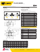
The listed C
v
“factors” are derived from actual flow testing, at Apollo’s Pageland, South Carolina factory. These tests were completed using standard
“o the shelf” valves with no special preparation and utilizing standard schedule 40 pipe. It should be understood that these factors are for the valve
only and also include the connection configuration. The flow testing is done utilizing water as a fluid media and is a direct statement of the gallons of
water flowed per minute with a 1 psig pressure dierential across the valve/connection unit. Line pressure is not a factor. Because the C
v
is a factor, the
formula can be used to estimate flow of most media for valve sizing.
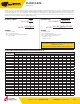
CV FACTORS FOR APOLLO
VALVES (CONTINUED ON M-4)
VALVE
SIZE (IN.)
1/4 3/8 1/2 3/4 1 1.25 1.5 2 2.5 3 4 6 8 10 12
70B-140 Series 8.4 7.2 15 30 43 48 84 108 190 370 670 -- -- -- --
70-100/200 Series 8.4 7.2 15 30 43 48 84 108 190 370 670 -- -- -- ---
70-300/400 Series -- -- 15 30 43 48 84 108 -- -- -- -- -- -- --
70-600 Series 2.3 4.5 5.4 12 14 21 34 47 -- -- -- -- -- -- --
70-800 Series 8.4 7.2 15 30 43 48 84 -- -- -- -- -- -- -- --
71-AR Series -- -- -- 30 43 48 84 108 190 370 -- -- -- -- --
71-100/200 Series -- -- -- 30 43 48 84 108 190 370 -- -- -- -- --
72-100/900 Series -- -- 26 48 65 125 170 216 -- -- -- -- -- -- --
72-1xx-A/72-9xx-A Series -- -- 26 48 65 125 170 245 -- -- -- -- -- -- --
73A-100 Series 8.4 7.2 15 30 43 48 84 108 -- -- -- -- -- -- --
73-300/400 Series -- -- 26 48 65 125 170 216 -- -- -- -- -- -- --
74-100 Series 8.4 7.2 15 30 43 48 84 108 190 370 670 -- -- -- --
75-100 Series 8.4 7.2 15 30 43 48 84 108 190 370 670 -- -- -- --
76-AR Series 8.4 7.2 15 30 43 48 84 108 190 370 670 -- -- -- --
76F-100 Series 8.1 15 15 51 68 125 177 389 -- -- -- -- -- -- --
76FJ-100 Series 8.1 15 15 51 68 125 177 389 -- -- -- -- -- -- --
76FK-100 Series 8.1 15 15 51 68 125 177 389 -- -- -- -- -- -- --
76-100 Series 8.4 7.2 15 30 43 48 84 108 190 370 -- -- -- -- --
76-300/400 Series -- -- 26 48 65 125 170 216 -- -- -- -- -- -- --
76-600 Series 2.3 4.5 5.4 12 14 21 34 47 -- -- -- -- -- -- --
76J-100 Series 8.4 7.2 15 30 43 48 84 108 190 370 -- -- -- -- --
76J-AR Series 8.4 7.2 15 30 43 48 84 108 190 370 670 -- -- -- --
76K-100 Series 8.4 7.2 15 30 43 48 84 108 190 370 -- -- -- -- --
76K-AR Series 8.4 7.2 15 30 43 48 84 108 190 370 670 -- --
-- --
7K-100 Series -- -- 15 51 68 125 177 389 503 -- -- -- -- -- --
77-AR Series 8.1 15 15 51 68 -- 177 389 -- -- -- -- -- -- --
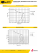
∆P
SpGr
Q = C
V
√
FLOW OF LIQUID
WHERE:
• Q = Flow in US gpm
• ∆P = Pressure drop (psig)
• SpGr = Specific gravity at flowing temperature
• C
v
= Valve constant
FLOW OF GAS
WHERE:
• Q = Flow in SCFH
• ∆P = Pressure drop (psig)
• SpGr = Specific gravity (based on air = 1.0)
• P2 = Outlet pressure–psia (psig + 14.7)
• T = (temp. °F + 460)
• C
v
= Valve constant
(Q)
2
(SpGr)
(C
v
)
2
or ∆P =
(∆P) (P
2)
(SpGr) (T)
Q = 1360 C
V
√
5.4 x 10
-7
(SpGr) (T) (Q)
2
(Cv)
2
(P2)
or ∆P =
CAUTION: The gas equation shown, is valid at very low pressure drop ratios.
The gas equation is NOT valid when the ratio of pressure drop (∆P) to inlet
pressure (P1) exceeds 0.02.
NOTE: Only use the gas equation shown if (P1-P2)/P1 is less than 0.02.
REV. 21APR17
FLOW DATA
FLOW DATA