Applied Radar, Inc. www.appliedradar.com AR2010 USB Stick Synthesizer Generation II USB Programming Manual Revision 1.0.
AR2010 USB Stick Synthesizer Notices © Applied Radar, Inc. 2011 No part of this manual may be reproduced in any form or by any means (including electronic storage and retrieval or translation into a foreign language) without prior permission and written consent from Applied Radar, Inc. as governed by United States and international copyright laws. Manual Part Number AR2010-99-2 Edition Revision 1.0.0, August 2011 Printed in the USA Applied Radar, Inc.
AR2010 USB Stick Synthesizer USB Programming Manual Restricted Rights Legend The Software and Documentation have been developed entirely at private expense. They are delivered and licensed as "commercial computer software" as defined in DFARS 252.227-7013 (Oct 1988), DFARS 252.211-7015 (May 1991), or DFARS 252.227-7014 (Jun 1995), as a "commercial item" as defined in FAR 2.101(a) or as "restricted computer software" as defined in FAR 25.
AR2010 USB Stick Synthesizer USB Programming Manual Any interruption of the protective conductor, inside or outside the product, is likely to make the product dangerous. Intentional interruption is prohibited. If this product is not used as specified, the protection provided by the equipment could be impaired. This product must be used in a normal condition (in which all means of protection are intact) only. No operator serviceable parts inside. Refer servicing to qualified personnel.
AR2010 USB Stick Synthesizer USB Programming Manual Markings The following markings may appear on the equipment or in any related documentation. J ESD Sensitive This marking indicates that a device, or part of a device, may be susceptible to electrostatic discharges (ESD) which can result in damage to the product. Observed ESD precautions given on the product, or in its user documentation, when handling equipment bearing this mark.
AR2010 USB Stick Synthesizer USB Programming Manual This marking indicates that the device communicates over the Universal Serial Bus (USB). This marking indicates that the device communicates over Ethernet. This marking indicates that the device is USB Low Speed and Full Speed certified. This marking indicates that the device is USB On The Go (OTG) Low Speed and Full Speed certified. This marking indicates that the device is USB High Speed certified.
AR2010 USB Stick Synthesizer USB Programming Manual Revision Control Revision 1.0.0 Description of Changes Date Initial Creation 08/18/2011 Applied Radar, Inc. Revision 1.0.
AR2010 USB Stick Synthesizer Applied Radar, Inc. USB Programming Manual Revision 1.0.
AR2010 USB Stick Synthesizer USB Programming Manual Contents Notices . . . . . . . . . . . . . . . . . . Manual Part Number . . . . . Edition . . . . . . . . . . . . . Trademark Acknowledgements Warranty . . . . . . . . . . . . Technology Licenses . . . . . Restricted Rights Legend . . . Safety Notices . . . . . . . . . Restricted Rights Legend . . . General Warranty . . . . . . . Product Safety . . . . . . . . . . . . . . Safety Notices . . . . . . . . . . . . Personal Safety Considerations . . .
AR2010 USB Stick Synthesizer 1.7 1.8 USB Programming Manual 1.6.6 Definition . . . . . . 1.6.7 Definition . . . . . . 1.6.8 Definition . . . . . . 1.6.9 Definition 1.6.10 Definition . . . . . Input Message Terminators . . . . . Compliance Information . . . . . . . 1.8.1 IEEE-488.2 Compliance . . 1.8.2 SCPI Compliance . . . . . . 1.8.3 USBTMC Compliance . . . . 1.8.4 VISA Compliance . . . . . . 3 Command Quick Reference Guide 1. Common (*) Commands . . . . . . .
AR2010 USB Stick Synthesizer 3. 4. 5. 6. 7. 8. 9. 10. 11. 12. 13. 14. 15. 16. USB Programming Manual *ESE . . . . . . . . . . . . . . . *ESR? . . . . . . . . . . . . . . . . . . *IDN? . . . . . . . . . . . . . . . . . . . *OPC . . . . . . . . . . . . . . . . . . . *OPT? . . . . . . . . . . . . . . . . . . *RCL . . . . . . . . . . . . . . . *RST . . . . . . . . . . . . . . . . . . . *SAV . . . . . . . . . . . . . . . *SRE . . . . . . . . . . . . . . . *STB? . . . . . . . . . . . . .
AR2010 USB Stick Synthesizer USB Programming Manual List of Tables 2.2 Default Units . . . . . . . . . . . . . . . . . . . . . . . . . . . . . . . . . . . . . . . . . . . 3.1 3.2 3.3 3.4 Common (*) Commands Summary . . . . . . . FREQuency subsystem Commands Summary POWER subsystem Commands Summary . . SYSTem subsystem Commands Summary . . . . . . . . . . . . . . . . . . . . . . . . . . . . . . . . . . . . . . . . . . . . . . . . . . . . . . . . . . . . . . . . . . . . . . . . . . . . .
AR2010 USB Stick Synthesizer USB Programming Manual 1 Product Overview In This Chapter 1. AR2010-4400 USB Stick Synthesizer Overview . . . . . . . . . . . . . . . . . . . . . . . . . . 3 2. Part Number . . . . . . . . . . . . . . . . . . . . . . . . . . . . . . . . . . . . . . . . . . . . . 3 Applied Radar, Inc. Revision 1.0.
AR2010 USB Stick Synthesizer USB Programming Manual 1. AR2010-4400 USB Stick Synthesizer Overview The AR2010 USB Stick Synthesizer product line is a low-cost, wideband PLL based frequency synthesizer ideally suited for bench top test and measurement as well as low-cost small form-factor radar and communications systems. The AR2010 is USB bus powered so it must be connected to a USB port on the computer or through powered USB hub for operation. The output power of the AR2010 is user adjustable in 0.
AR2010 USB Stick Synthesizer USB Programming Manual 2 Remote Operation In This Chapter 1. Introduction . . . . . . . . . . . . . . . . . . . . . . . . . . . . . . . . . . . . . . . . . . . . . . 6 1.1 USB Configuration . . . . . . . . . . . . . . . . . . . . . . . . . . . . . . . . . . . . . . . . . . . 6 1.2 Command Syntax . . . . . . . . . . . . . . . . . . . . . . . . . . . . . . . . . . . . . . . . . . . 6 1.2.1 Mnemonic Forms . . . . . . . . . . . . . . . . . . . . . . . . . . . . . . . .
AR2010 USB Stick Synthesizer USB Programming Manual 1.8.3 USBTMC Compliance . . . . . . . . . . . . . . . . . . . . . . . . . . . . . . . . . . . . . 11 1.8.4 VISA Compliance 11 . . . . . . . . . . . . . . . . . . . . . . . . . . . . . . . . . . . . . . . The following markings apply to the AR2010 USB Stick Synthesizer family of products. J ESD Sensitive Applied Radar, Inc. Revision 1.0.
AR2010 USB Stick Synthesizer USB Programming Manual 1. Introduction 1.1 USB Configuration The Applied Radar AR2010 USB Stick Synthesizer has been designed to configure as a USB Test and Measurement Class (USBTMC) device. No additional drivers are required.
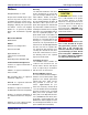
AR2010 USB Stick Synthesizer USB Programming Manual ∙ Ovals enclose command mnemonics. The command mnemonic must be entered exactly as shown in the oval. ∙ Dotted lines indicate an optional path for passing secondary or optional keywords. ∙ Arrows and curved intersections indicate command path direction. ∙ All diagrams flow from left to right. A path may not travel to the left except in a bypass loop. 1.4 Default Units Unless otherwise specified, the following units are assumed: Table 2.
AR2010 USB Stick Synthesizer USB Programming Manual 1.6.2 Definition Throughout this document, is used to represent character data, that is, A-Z, a-z, 09 and _ (underscore). STOP and A4_U2 are examples of character data. The first character must be alphanumeric, followed by either alphanumeric or underscore characters up to a maximum of 12 characters. 1.6.3 Definition Not a number (NAN) is represented as 9.91 E37. Not a number is defined in IEEE 754. 1.6.
AR2010 USB Stick Synthesizer ∙ ∙ ∙ ∙ USB Programming Manual 12.7 +127 -1.2345 -0.123 1.6.8 Definition Throughout this document, numeric response data is defined as: + ∙ Digit Digit - + E Digit - The following shows the examples of : ∙ 1.23E+4 ∙ 12.3E-45 1.6.9 Definition Throughout this document, the decimal numeric element is abbreviated to . 1.6.
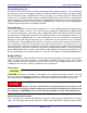
AR2010 USB Stick Synthesizer USB Programming Manual Program Data ’ ’ ’ " " " Response Data " " " 1.7 Input Message Terminators Program messages sent to a SCPI instrument must terminate with a character. The IEEE.488 EOI (end or identify) signal is interpreted as a character and may also be used to terminate a message in place of the character.
AR2010 USB Stick Synthesizer USB Programming Manual 1.8.3 USBTMC Compliance The AR2010 USB Stick Synthesizer complies with the rules and regulations of the of the USBTMC (USB Test and Measurement Class). When connected to a USB bus, the AR2010 will configure as a USB Test and Measurement device. 1.8.4 VISA Compliance The AR2010 USB Stick Synthesizer complies with the rules and regulations of the of the VISA (Virtual Instrument Systems Architecture) standard.
AR2010 USB Stick Synthesizer USB Programming Manual 3 Command Quick Reference Guide In This Chapter 1. Common (*) Commands . . . . . . . . . . . . . . . . . . . . . . . . . . . . . . . . . . . . . . . 13 2. FREQuency Subsystem . . . . . . . . . . . . . . . . . . . . . . . . . . . . . . . . . . . . . . . 14 3. POWER Subsystem . . . . . . . . . . . . . . . . . . . . . . . . . . . . . . . . . . . . . . . . . 14 4. SYSTem Subsystem . . . . . . . . . . . . . . . . . . . . . . . . . . . . . . . . . . . .
AR2010 USB Stick Synthesizer USB Programming Manual 1. Common (*) Commands Table 3.1: Common (*) Commands Summary Command Page Description *CLS 44 Clears the data structures. The SCPI registers are cleared. *ESE 45 Sets the Standard Event Status Enable Register. *ESE? 45 Returns the Standard Event Status Enable Register. *ESR? 46 Returns the contents of the Standard Event Status Register and then clears it.
AR2010 USB Stick Synthesizer USB Programming Manual 2. FREQuency Subsystem Table 3.2: FREQuency subsystem Commands Summary Command Page Description FREQuency:LOCK 16 Returns the lock status of the device. FREQuency:REFerence:EXTernal 19 Sets or Returns whether the internal or external supplied reference oscillator is used. FREQuency:SET 20 Sets or Returns the desired tuning frequency frequency in GHz. 3. POWER Subsystem Table 3.
AR2010 USB Stick Synthesizer USB Programming Manual 4 FREQuency Subsystem In This Chapter 1. FREQuency:LOCK . . . . . . . . . . . . . . . . . . . . . . . . . . . . . . . . . . . . . . . . . . 16 2. FREQuency:PLLMode . . . . . . . . . . . . . . . . . . . . . . . . . . . . . . . . . . . . . . . . 17 3. FREQuency:REFerence:EXTernal . . . . . . . . . . . . . . . . . . . . . . . . . . . . . . . . . 19 4. FREQuency:SET . . . . . . . . . . . . . . . . . . . . . . . . . . . . . . . . . . . . . . . . . . .
AR2010 USB Stick Synthesizer USB Programming Manual 1. FREQuency:LOCK? This command returns the lock status of the USB Stick Synthesizer. A lock status of 0 indicates that the device is unlocked, while a lock status of 1 indicates that the device is locked. Syntax FREQ :LOCK ? Query Example FREQ:LOCK? This query returns the lock status of the device Applied Radar, Inc. Revision 1.0.
AR2010 USB Stick Synthesizer USB Programming Manual 2. FREQuency:PLLMode [INT|FRAC|1|0] This command sets the Phase Lock Loop (PLL) mode of the USB Stick Synthesizer. A PLL mode of INT or 1 indicates that the PLL is operating in Integer mode, while a PLL mode of FRAC or 0 indicates that the PLL is operating in Fractional Mode. When the PLL is placed in Integer mode (also referred to as Integer-N mode), the output frequency is an integer multiple of the reference oscillator frequency.
AR2010 USB Stick Synthesizer USB Programming Manual Default Condition On power up, or when a SYST:PRES or *RST command is issued, the PLL mode setting defaults to the mode stored in memory location 0, unless otherwise specified in the product’s Operation Manual. Query Example FREQ:PLLM? This query returns the PLL mode of the device. ∙ 0 is returned if the synthesizer is Fractional Mode ∙ 1 is returned if the synthesizer is in Integer Mode Applied Radar, Inc. Revision 1.0.
AR2010 USB Stick Synthesizer USB Programming Manual 3. FREQuency:REFerence:EXTernal [ON|OFF|1|0] This command allows the user to select between the internal 10 MHz reference and an externally supplied 10 MHz reference. When OFF or 0 is specified, the internal reference oscillator is used by the USB Stick Synthesizer. When ON or 1 is specified, the external reference input is used by the USB Stick Synthesizer.
AR2010 USB Stick Synthesizer USB Programming Manual 4. FREQuency:SET This command allows the user to set the frequency of the USB Stick Synthesizer. The frequency value is specified in MHz.
AR2010 USB Stick Synthesizer USB Programming Manual 5 POWEr Subsystem In This Chapter 1. POWEr:RF . . . . . . . . . . . . . . . . . . . . . . . . . . . . . . . . . . . . . . . . . . . . . . 22 2. POWEr:SET . . . . . . . . . . . . . . . . . . . . . . . . . . . . . . . . . . . . . . . . . . . . . 23 Applied Radar, Inc. Revision 1.0.
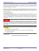
AR2010 USB Stick Synthesizer USB Programming Manual 1. POWEr:RF [ON|OFF|1|0] This command allows the user to turn on and off the RF output of the USB Stick Synthesizer. Syntax POWE :RF Space ON|OFF|1|0 ? Example POWE:RF 0 This command turns off the RF. Default Condition On power up, or when a SYST:PRES or *RST command is issued, the USB Stick Synthesizer RF output defaults to the RF OFF state, unless otherwise specified in the product’s Operation Manual.
AR2010 USB Stick Synthesizer USB Programming Manual 2. POWEr:SET [|MIN |MAX] This command allows the user to set the output power of the AR2010 in 0.5 dB steps with a ±0.25 dBm accuracy. The output power value is specified in dBm and rounded to the nearest 0.5 dBm. See your Product’s Configuration Sheet for valid output power ranges. Selecting MAX or MIN configures the AR2010 to output the maximum and minimum power levels, respectively, achievable at the current frequency.
AR2010 USB Stick Synthesizer USB Programming Manual 6 SYSTem Subsystem In This Chapter 1. SYSTem:CLeaRMemory . . . . . . . . . . . . . . . . . . . . . . . . . . . . . . . . . . . . . . . 25 2. SYSTem:ERRor . . . . . . . . . . . . . . . . . . . . . . . . . . . . . . . . . . . . . . . . . . . 26 3. SYSTem:FIRMware . . . . . . . . . . . . . . . . . . . . . . . . . . . . . . . . . . . . . . . . . 30 4. SYSTem:LOAD . . . . . . . . . . . . . . . . . . . . . . . . . . . . . . . . . . . . . . . . . . . .
AR2010 USB Stick Synthesizer USB Programming Manual 1. SYSTem:CLeaRMemory [1-9] This command clears the specified memory location. Memory location 0 is a protected memory location and can not be cleared. To erase the parameters stored in Memory location 0, use the SYSTem:RESTore command to overwrite the parameters stored in Memory Location 0 with the factory defaults. Syntax SYST :CLRM Space 1-9 Example SYST:CLRM 3 This command clears memory location 3. Applied Radar, Inc. Revision 1.0.
AR2010 USB Stick Synthesizer USB Programming Manual 2. SYSTem:ERRor? This query returns error numbers and messages from the AR2010 error queue. When an error is generated by the AR2010, the error number and corresponding error message is stored in the error queue. Each time the error queue is queried, the first error in the error queue is returned. The errors are read out in the order of first-in first-out. To clear all errors in the error queue, use the *CLS command.
AR2010 USB Stick Synthesizer -113 USB Programming Manual Undefined header A command was received that is not valid for the USB Stick Synthesizer. -121 Invalid character in number An invalid character was found in the number specified for a parameter value. -123 Exponent too large A numeric parameter was found whose exponent was larger than 32,000. -124 Too many digits A numeric parameter was found whose mantissa contained more than 255 digits.
AR2010 USB Stick Synthesizer USB Programming Manual Indicates that a trigger command was received but ignored because the USB Stick Synthesizer was not in the wait for trigger state. -213 Trigger ignored Indicates that a trigger command was received but ignored because the USB Stick Synthesizer was not in the wait for trigger state. -222 Data out of range A numeric parameter value is outside the valid range for the command.
AR2010 USB Stick Synthesizer USB Programming Manual No errors in the error queue. Device is operating normally. +110 Invalid Command For Specified Device The issued command is invalid for the specified device. Applied Radar, Inc. Revision 1.0.
AR2010 USB Stick Synthesizer USB Programming Manual 3. SYSTem:FIRMware? This command returns the current software firmware of the AR2010. Syntax Syntax SYST :FIRM ? Query Example SYST:FIRM? This query returns the current firmware version of the USB Stick Synthesizer. Applied Radar, Inc. Revision 1.0.
AR2010 USB Stick Synthesizer USB Programming Manual 4. SYSTem:LOAD [0-9] This command loads the settings from the specified memory location. There are 10 memory locations, with location 0 being the default location which is restored upon power-on or reset. For a detailed description of the parameters saved, see your product’s Operation Manual. Syntax SYST :LOAD Space 0-9 There are 10 memory locations, numbered 0 through 9.
AR2010 USB Stick Synthesizer USB Programming Manual 5. SYSTem:MODelNUMber? This command returns the model number of the device. SYST :MODNUM ? Query Example SYST:MODNUM? Applied Radar, Inc. This query returns the model number of the device. Revision 1.0.
AR2010 USB Stick Synthesizer USB Programming Manual 6. SYSTem:PRESet The SYSTem:PRESet command returns the USB Stick Synthesizer to its initial power-up state. Syntax SYST :PRES Applied Radar, Inc. Revision 1.0.
AR2010 USB Stick Synthesizer USB Programming Manual 7. SYSTem:OPTions? This command returns the installed options from the device. The options are returned as a comma separated string of option codes. If no options are installed, a 0 is returned. Syntax SYST :OPT ? Query Example SYST:OPT? This query returns the installed options of the device. Applied Radar, Inc. Revision 1.0.
AR2010 USB Stick Synthesizer USB Programming Manual 8. SYSTem:READSTRing? This command reads a string, unaltered, from the device. CAUTION The string is read directly from the device. No error checking or formatting is performed. USE WITH EXTREME CAUTION! Syntax SYST :READSTR ? Allowed Values The returned string can be any ASCII string with a maximum length of 256 characters. Query Example SYST:READSTR? Applied Radar, Inc. This command reads a string from the device. Revision 1.0.
AR2010 USB Stick Synthesizer USB Programming Manual 9. SYSTem:RESTore This command restores the AR2010 to the factory default state. Memory location 0 is overwritten with the factory default settings. For a detailed description of the parameters saved, see your product’s Operation Manual. Syntax SYST :REST Example SYST:REST This command restores the factory default settings to memory location 0 Applied Radar, Inc. Revision 1.0.
AR2010 USB Stick Synthesizer USB Programming Manual 10. SYSTem:SAVE [0-9] This command saves the current setup to memory. There are 10 memory locations, with location 0 being the default location which is restored upon power-on or reset. For a detailed description of the parameters saved, see your product’s Operation Manual. Syntax SYST :SAVE Space 0-9 There are 10 memory locations, numbered 0 through 9.
AR2010 USB Stick Synthesizer USB Programming Manual 11. SYSTem:SENDSTRing This command sends a string, unaltered, to the device. CAUTION The supplied string is passed directly to the device. No error checking is performed. USE WITH EXTREME CAUTION! Syntax SYST :SENDSTR Space string value Allowed Values The can be any ASCII string with a maximum of 256 characters. Example SYST:SENDSTR "RESET;" Applied Radar, Inc. This command sends the string RESET; to the device.
AR2010 USB Stick Synthesizer USB Programming Manual 12. SYSTem:SERialNUMber? This command returns the serial number of the device. Syntax SYST :SERNUM ? Query Example SYST:SERNUM? Applied Radar, Inc. This query returns the serial number of the device. Revision 1.0.
AR2010 USB Stick Synthesizer USB Programming Manual 13. SYSTem:STATus? This command returns the status of the USB Stick Synthesizer. Syntax SYST :STAT ? Query Example SYST:STAT? This query returns the status of theUSB Stick Synthesizer. Status messages have the following format: Status Number , " Status Description " For example, 0, "Operational" Status Message List Table 6.
AR2010 USB Stick Synthesizer USB Programming Manual 14. SYSTem:VERSion? This query returns the version of SCPI used in the USB Stick Synthesizer. The respeonse is in the format XXXX.Y, where XXXX is the year and Y is the version number. Syntax SYST :VERS ? Query Example SYST:VERS? This query returns the version of SCPI used in the USB Stick Synthesizer. Applied Radar, Inc. Revision 1.0.
AR2010 USB Stick Synthesizer USB Programming Manual 7 IEEE 488.2 Command Reference In This Chapter 1. SCPI Compliance Information . . . . . . . . . . . . . . . . . . . . . . . . . . . . . . . . . . . . 43 2. *CLS . . . . . . . . . . . . . . . . . . . . . . . . . . . . . . . . . . . . . . . . . . . . . . . . . 44 3. *ESE . . . . . . . . . . . . . . . . . . . . . . . . . . . . . . . . . . . . . . . . . . . . . 45 4. *ESR? . . . . . . . . . . . . . . . . . . . . . . . . . . . . . . . . . . . . .
USB Stick Synthesizer IEEE 488.2 Command Reference 1. SCPI Compliance Information This chapter contains information on the IEEE-488 Common Commands that the USB Stick Synthesizer supports. The IEEE-488.2 Common Command descriptions are listed below. Table 7.1: IEEE 488.2 Common commands Applied Radar, Inc.
USB Stick Synthesizer IEEE 488.2 Command Reference 2. *CLS The *CLS (CLear Status) command clears the data structures. The SCPI registers are all cleared. Syntax *CLS Applied Radar, Inc. Revision 1.0.
USB Stick Synthesizer IEEE 488.2 Command Reference 3. *ESE The *ESE (Event Status Enable) command sets the Standard Event Status Enable Register. This register contains a mask value for the bits to be enabled in the Standard Event Status Register. A 1 in the enable register enables the corresponding bit in the Status Register, a 0 disables the corresponding bit in the Status Register.
USB Stick Synthesizer IEEE 488.2 Command Reference 4. *ESR? The *ESR? query returns the contents of the Standard Event Status Register then clears it. The returned value is in the range of 0 to 255. Table 7.3 shows the contents of this register. Table 7.3: *ESR? mapping Bit Base 2 Meaning 0 1 Operation Complete 1 2 Not Used 2 4 Query Error 3 8 Device Dependent Error 4 16 Execution Error 5 32 Command Error 6 64 Not Used 7 128 Power On Syntax *ESR Applied Radar, Inc.
USB Stick Synthesizer IEEE 488.2 Command Reference 5. *IDN? The *IDN? query allows the connected device to identify itself. The string returned is: Applied Radar,,,, where: ∙ ∙ ∙ ∙ identifies the product number of the host uniquely identifies the host returns the firmware of the host returns the device id of the host Syntax *IDN Applied Radar, Inc. ? Revision 1.0.
USB Stick Synthesizer IEEE 488.2 Command Reference 6. *OPC The *OPC (Operation Complete) command causes the AR2010 USB Stick Synthesizer to set the operation complete bit in the Standard Event Status Register when all pending device operations have been completed. Table 7.
USB Stick Synthesizer IEEE 488.2 Command Reference 7. *OPT? The *OPT? query reports the options installed in the AR2010 USB Stick Synthesizer and returns " " empty string if no options have been installed. Syntax *OPT Applied Radar, Inc. ? Revision 1.0.
USB Stick Synthesizer IEEE 488.2 Command Reference 8. *RCL The *RCL (ReCaLl) command restores the state of the AR2010 USB Stick Synthesizer from the specified save or recall register. Valid register addresses are 0 to 9. A configuration must have been stored previously in the specified register. Syntax *RCL Space NRf Allowed Values The NRf parameter can be any integer in the range of 0 to 9.
USB Stick Synthesizer IEEE 488.2 Command Reference 9. *RST The *RST (ReSeT) command returns the AR2010 USB Stick Synthesizer to its initial power-up state. Syntax *RST Applied Radar, Inc. Revision 1.0.
USB Stick Synthesizer IEEE 488.2 Command Reference 10. *SAV The *SAV (SAVe) command restores the state of the AR2010 USB Stick Synthesizer from the specified save or recall register. Valid register addresses are 0 to 9. A configuration must have been stored previously in the specified register. Syntax *SAV Space NRf Allowed Values The NRf parameter can be any integer in the range of 0 to 9. Applied Radar, Inc. Revision 1.0.
USB Stick Synthesizer IEEE 488.2 Command Reference 11. *SRE The *SRE command sets the Service Request Enable register bits. This register contains a mask value for the bits to be enabled in the Status Byte Register. A 1 in the enable register enables the corresponding bit in the Status Register, a 0 disables the corresponding bit in the Status Register. The parameter value when expressed in base 2, represents bits 0 to 5 and bit 7 of the Service Request Enable Register.
USB Stick Synthesizer IEEE 488.2 Command Reference 12. *STB? The *STB? (STatus Byte) query returns bit 0 to 5 and bit 7 of the AR2010 USB Stick Synthesizer status byte and returns the Master Summary Status (MSS) as bit 6. The MSS is inclusive OR of the bitwise combination (excluding bit 6) of the Status Byte and the Service Request Enable registers. The format of the return is an integer between 0 and 255. Table 7.6 shows the contents of this register. Table 7.
USB Stick Synthesizer IEEE 488.2 Command Reference Syntax *STB ? Applied Radar, Inc. Revision 1.0.
USB Stick Synthesizer IEEE 488.2 Command Reference 13. *TRG The *TRG (TRiGger) command triggers the AR2010 USB Stick Synthesizer when it is in the waiting for trigger state. Syntax *TRG Error Message If the USB Stick Synthesizer is not in the wait-for-trigger state, error 210, "Trigger Ignored occurs. Applied Radar, Inc. Revision 1.0.
USB Stick Synthesizer IEEE 488.2 Command Reference 14. *TST? The *TST? query causes the AR2010 USB Stick Synthesizer to perform a self-test. The result of the self-test is placed in the output queue. ∙ 0 is returned if the test passes ∙ 1 is returned if the test fails Syntax *TST Applied Radar, Inc. ? Revision 1.0.
USB Stick Synthesizer IEEE 488.2 Command Reference 15. *WAI The *WAI (WAIt)) command causes the AR2010 USB Stick Synthesizer to wait until either: ∙ All pending operations are complete ∙ The Device Clear command is received ∙ Power is cycled before executing any subsequent commands or queries. Syntax *WAI Applied Radar, Inc. Revision 1.0.
USB Stick Synthesizer IEEE 488.2 Command Reference 16. USBTMC/USB488 Universal Commands DCL The DCL (Device CLear) command causes all USB instruments to assume a cleared condition. The definition of Device Clear is unique for each instrument. For the AR2010 USB Stick Synthesizer: ∙ All pending operations are halted ∙ The parser (the software that interprets the programming codes) is reset and is waiting for the first character of a programming code. ∙ The output buffer is cleared.
USB Stick Synthesizer IEEE 488.2 Command Reference Index FREQuency Subsystem FREQuency:LOCK, 16 FREQuency:PLLMode, 17 FREQuency:REFerence:EXTernal, 19 FREQuency:SET, 20 IEEE 488.
USB Stick Synthesizer IEEE 488.2 Command Reference SCPI Compliance, 10 USBTMC Compliance, 11 VISA Compliance, 11 Default Units, 7 Diagram Syntax Conventions, 6 Input Message Terminators, 10 Part Number, 3 SCPI Data Types, 7 Status Reporting, 7 USB, 6 Notices, i POWEr Subsystem, 21 Product Overview, 2 Product Safety, ii Remote Operation, 4 SYSTem Subsystem, 24 Applied Radar, Inc. Revision 1.0.
@AR2010-99-2@ AR2010-99-2 Revision 1.0.0, August 2011 Applied Radar, Inc. www.appliedradar.