HANDBOOK A8 5 P8 5 P8 5 / 3 Arcam A85, P85 and P85/3 amplifiers Amplificateurs Arcam A85, P85 et P85/3 Arcam-Verstärker A85, P85 und P85/3 A85/P85 multi.
Safety guidelines Safety instructions This product is designed and manufactured to meet strict quality and safety standards. However, you should be aware of the following installation and operation precautions: 1. Take heed of warnings and instructions You should read all the safety and operating instructions before operating this appliance. Retain this handbook for future reference and adhere to all warnings in the handbook or on the appliance. 2.
This handbook has been designed to give you all the information you need to install, connect, set up and use the Arcam A85 integrated amplifier or the P85 power amplifier. The A85 amplifier is described first, then the P85. The CR-389 remote control handset supplied with the A85 integrated amplifier is also described. Your amplifier(s) may have been installed and set up by an authorised Arcam dealer. In this case, you may wish to go directly to the sections describing the use of this equipment.
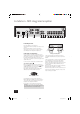
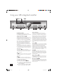
Installation: A85 integrated amplifier L PHONO R SP2 230V VOLTAGE SELECT 4 – 16 OHMS TRIG OUT + 2 R – 3 MM MC L INTEGRATED R REMOTE IN POWER INLET 1 L SP1 + L – 4 R PRE/PWR PWR IN PRE OUT 567 RECORD PLAY OUT IN TAPE 1 RECORD PLAY OUT IN VCR/TAPE 2 DVD AV TUNER CD AUX 8 9 bk bl bm bn bo bp bq br Positioning the unit Arcam A85 amplifier + Place your amplifier on a level, firm surface. – + – L R Avoid placing the unit in direct sunlight or near sources of heat or damp.
Connecting to a power supply bn Wrong plug? bo Check that the plug supplied with the unit fits your supply and that your mains supply voltage agrees with the voltage setting (115V or 230V) indicated on the rear panel of the unit before plugging in. TUNER – Connect this input to the audio outputs of your radio tuner. If your mains supply voltage or mains plug is different, consult your Arcam dealer or Arcam Customer Support on +44 (0)1223 203203.
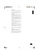
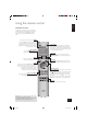
Using your A85 integrated amplifier 9 bk bl bm bnbo A85 INTEGRATED AMPLIFIER RECORD MODE ENTER SELECT PHONES PHONO/AUX CD TUNER 1 AV DVD VCR 2 3 Front panel controls SP1 4 5 6 SP2 7 POWER 8 The light indicates the status of the amplifier. A red light means the amplifier is in standby mode (press the Power/Standby button on the remote control, or the POWER button on the front panel, to switch between standby and powered-up modes).
Recording E ng l i s h With the Arcam A85 it is possible to listen to and record from one source, or to listen to one source while recording another. Both sets of tape sockets are identical in sensitivity and suitable for use with almost any type of recorder (cassette, CDR, MD, VCR, reel-to-reel, etc.). The record signal is sent to both the TAPE and VCR output sockets. bk RECORD To record the currently selected source, press RECORD until the display shows ‘RECORD SOURCE’.
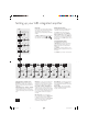
Setting up your A85 integrated amplifier ‘Switch on’ state DOWN UP VOLUME Adjust LEFT Introduction Adjusting listening settings The A85 allows you to adjust listening settings to suit your taste, and to customize various features of the amplifier to fit your system. Use this diagram to help you navigate through the settings available. The default display mode is VOLUME, where the control knob is used to adjust sound level.
E ng l i s h Using the remote control CR-389 Remote Control The CR-389 remote control gives access to all functions available on the front panel of the A85. It also has controls to operate Arcam CD players, AM/FM tuners and DAB tuners. The remote control transmits Philips RC-5 type codes. TUNER These buttons are used to control tuner functions. Note that the FM/DAB lights indicate into which mode you are switching the remote control. The lights only illuminate for five seconds to conserve battery power.
Installation: P85 power amplifer + R/CH1 – + L/CH2 – + CTR/CH3 – SP2 SP2 AUDIO 4 – 16 OHMS TRIG OUT 230V VOLTAGE SELECT LINK CTR/CH3 4 – 16 OHMS L R REMOTE IN + R/CH1 – POWER INLET AUDIO IN SP1 SP1 + L/CH2 – OUT IN + CTR/CH3 – OUT Optional Third Channel Module – provides a third 85W channel suitable for Home Cinema or multi-channel audio use. Connecting to power, loudspeakers and other equipment Follow the installation instructions for the integrated amplifier on pages 4–6.
E ng l i s h Using your P85 power amplifier P85 POWER AMPLIFIER POWER SP1 SP2 POWER POWER (and power indicator light) SP1 and SP2 Switches the unit on and off. The light indicates the status of the amplifier. These buttons allow you to select and deselect the main (SP1) and secondary (SP2) sets of speakers attached to your amplifier. An indicator light shows which set of speakers are currently selected.
Bi-wiring and bi-amping loudspeakers Before you start Bi-amping your system WARNING: Do not make any connections to your amplifier while it is switched on or connected to the mains supply. Before switching on please check all connections thoroughly, making sure bare wires or cables are not touching the amplifier in the wrong places (which could cause short circuits) and you have connected positive (+) to positive and negative (–) to negative.
Before returning your amplifier for service, please check the following: Note that because of the high output voltage from a CD player, it is possible to drive the A85 at full power even though the volume is not set at maximum. Sound cuts out for no reason If the temperature of the internal heatsink rises above a safe level, then a thermal cutout inside the amplifier will operate. The power indicator on the front panel flashes and the protection system temporarily removes the power to the speakers.
Guarantee Worldwide Guarantee This entitles you to have the unit repaired free of charge, during the first two years after purchase, at any authorised Arcam distributor provided that it was originally purchased from an authorised Arcam dealer or distributor.