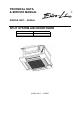
TECHNICAL DATA & SERVICE MANUAL INDOOR UNIT: ® AS52AL SPLIT SYSTEM AIR CONDITIONER Model No. AS52AL Product Code No. 387006130 0.8180.416.
• Ground the unit following local electrical codes. • The Yellow/Green wire cannot be used for any connection different from the ground connection. • Connect all wiring tightly. Loose wiring may cause overheating at connection points and a possible fire hazard. • Do not allow wiring to touch the refrigerant tubing, compressor, or any moving parts of the fan. • Do not use multi-core cable when wiring the power supply and control lines. Use separate cables for each type of line.
Table of Contents Page 4 4 5 6 1. SPECIFICATIONS 1-1 Unit specifications 1-2 Major Component specifications 1-3 Other Component specifications 2. DIMENSIONAL DATA 7 3. ELECTRICAL DATA 8 8 3-1 Electric Wiring Diagrams 9 9 10 11 12 13 13 15 18 18 18 19 4.
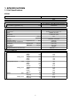
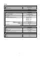
1. SPECIFICATIONS 1-1 Unit Specifications AS52AL Power source 220 - 240V ~ 50Hz Voltage rating 230V Performance Capacity Air circulation (High/Med.
AS52AL Controller PCB Part No. Controls Control circuit fuse KSA Microprocessor 250 V - 5 A Remote Control Unit RC-7 (RC) Fan & Fan Motor Type Q'ty ……. Dia. and lenght Fan motor model…Q'ty No. Of poles…rpm (230 V) Running Amps Power input Coil resistance (Ambient temp. 20 °C ) Safety devices mm A W Ω Type Operating temp. Open Close Run capacitor Flap Motor Type Model Rating No of poles …rpm Nominal output Coil resistance (Ambient temp. 20 °C ) °C °C µF VAC W kΩ Heat Exch.
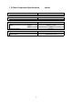
1-3 Other Component Specifications AS52AL Thermistor ( Coil sensor TH1) Resistance ΚΩ 10 ± 3% Thermistor ( Room sensor TH2) Resistance ΚΩ 10 ± 5% Drain pump Model Rating PC 309564003 220/240V - 50Hz 14W 0,4 l/min Voltage Input Total head capacity Safety float switch Model Contact rating BI 1300 2725 230V AC/DC - 0,5A 6
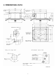
2.
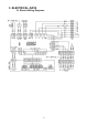
3.
4.
4-2 Heat Mode Operation 10
4-3 Auto (Cool/Heat) Mode Operation 11
4-4 Dry Mode Operation 12
4-5 Fan Mode Operation 4-6 Protection operations in Cool and Dry Mode 1.
2.
4-7 Protection Operations in Heat Mode 1.
2.
4-8 Sleep Function 4-9 Daily Timer Function 4-10 IFEEL Function 18
4-11 Pump Operation Drain pump operates only in Cool and Dry Mode. The float switch used for water level detection is closed under normal condition, and is open when wate overflow. For the NEC version of MCU, the "Overflow" and “Normal” conditions are indicated by a logic “0” and “1” at the float switch pins connector respectively. For the Fujitsu version of MCU, the "Overflow" and “Normal” condition are indicated by a logic “1” and “0” at the float switch pins connector respectively.
5. 6. TROUBLESHOOTING 5-1. 6-1. Check before and after troubleshooting WARNING Hazardous voltage can cause ELECTRIC SHOCK or DEATH. Disconnect power or turn off circuit breaker before you start checking or servicing. 6-1-1. Check power supply wiring. 5-1-1. ● Check that power supply wires are correctly connected to terminals L and N on the terminal plate in the indoor unit. 6-1-2. Check inter-unit wiring. 5-1-2.
B. Circuit breaker trips in several minutes after turning the air conditioner on. ● There is a possibility of short circuit. • Check capacity of circuit breaker. Replace with suitable one (larger capacity). NO Capacity of circuit breaker is suitable. In case of Heating operation : • Measure resistance of 4-way valve's winding. • Measure resistance of outdoor fan motor winding. • Measure resistance of compressor motor winding. 5-2-2. Neither indoor nor outdoor unit runs. 5-2-2. 6-2-2. A.
C. Check remote control unit. • Try to run with another remote control unit. OK First remote control unit is defective. • Check for residue buildup on transmitter of remote control unit. Clean transmitter. • Check for residue buildup on remote control receiver on front of indoor unit. Clean receiver. D. Check fuse on the indoor PCB Ass'y. • Check fuse on indoor PCB Ass'y for continuity. (F01) If fuse has been blown, Measure resistance of indoor and outdoor fan motor winding.
6-2-3. Only outdoor unit does not run. 5-2-3. A. Check setting temperature. COOL HEAT Is room temperature too low ? Is room temperature too high ? NO NO Try to lower setting temperature by temperature setting button ( button). Try to raise setting temperature by temperature setting button ( button). Outdoor unit still does not run. Outdoor unit still does not run. • Try to run using another remote control unit. • Try to run using another remote control unit.
5-3. Some part of air conditioner does not operate. 5-3-1. Only indoor fan does not run. • Check fan rotation. Turn fan gently once or twice by hand. • Check fan casing foreign matter on inside. Fan cannot be turned. Fan motor burnout or foreign matter in bearings. Remove foreign matter or repair. Repair or replace. • Measure resistance of indoor fan motor winding. OK • Check fan motor capacitor. OK PCB assy is defective. 5-3-2. Only flap motor does not run.
5-3-3. Only compressor does not run Check compressor motor Overload relay is working capacitor C1 (either OLR T or OLR A) YES Measure resistance of Temperature of compressor compressor motor winding is abnormally high YES Refrigerant gas shortage NO Measure power supply voltage NO Rotor may be locked up The voltage is too low 5-3-4.
5-4. Air conditioner operates, but abnormalities are observed 5-4-1.
6-4-2. Poor cooling or heating. 5-4-2. • Check position of remote control unit. • Cool or warm air from air conditioner reaches position directly. YES Change position of remote control unit. • Wide and narrow tubes between indoor unit and outdoor unit are insulated. NO Insulate both wide and narrow tubes separately and then tape together. (only with I FEEL feature selected) YES • Measure temperature of suction and discharge air of air conditioner. Temperature difference is small.
6-5 If a sensor is defective 6-5-1 ICT (indoor coil sensor) OCT(outdoor coil sensor) RAT (room ambient temperature) are defective. • Stand by lamp on front side of indoor unit is flashing on and off. (*) YES • Thermistor ICT and OCT and RAT are defective YES • Repalce thermistor. NOTE Allarm signal (*) Stan by lampoon on the front side of the indoor unit will flash on and off when the thermistor is defective. At the same time the outdoor unit will stop. Indoor operate only for ventilation.
6. CHECKING ELECTRICAL COMPONENTS 6-1 Measurement of Insulation Resistance power plug (Local supply) Ground The insulation is in good condition if the resistance exceeds 2MΩ probe Insulation tester NOTE 6-1-1. Power supply wires The shape of the power plug may differ from that of the air conditioner which you are servicing. Clamp the grounding terminal of the power plug with a lead clip of the insulation resistance tester and measure the resistance by placing a probe on both the two power terminals.
6-2 Checking Continuity of Fuse on PCB Ass'y Fuse Remove the PCB Ass'y from the electrical component box. Then pull out the fuse from the PCB Ass'y. (fig.5) PCB Ass’y Check for continuity using a multimeter as shown in fig.6 Fig. 5 Fuse Fig. 6 6-3 Checking Motor Capacitor Remove the lead wires from the capacitor terminals, and then place a probe on the capacitor terminals as shown in fig.7.
Via Varese, 90 - 21013 Gallarate - Va - Italy Tel. +39 0331 755111 - Fax +39 0331 776240 www.argoclima.