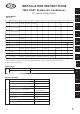
INSTALLATION INSTRUCTIONS - MULTISET System Air Conditioner - AS 1S DC Inverter 2-Way R410A R410A Models Indoor Units AS B S Indoor IndoorUnit UnitTTypeype 1-Way Air Dis charge AS 1S ** 1-W ay Air Discharge S emi-C oncealed S emi-C oncealed AS B S ** AS 2S ** 22 28 36 AS 1S 22MH AS 1S 28MH AS 1S 36MH AS B S 28MH AS B S 36MH AS B S 56MH AS B S 73MH 2-W 2-W ay ay Air Discharge 2-Way Air Discharge Dis charge 64 AS 2S 28MH AS 2S 36MH AS 2S 56MH AS 2S 73MH AS S 56MH* AS S 73MH* 106 73 1
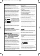
04-396 Inverter-W_a-p50 ARGO 12/21/04 9:38 AM Page 2 IMPORTANT! Please Read Before Starting When Installing… This air conditioning system meets strict safety and operating standards. As the installer or service person, it is an important part of your job to install or service the system so it operates safely and efficiently. …In a Room Properly insulate any tubing run inside a room to prevent “sweating” that can cause dripping and water damage to walls and floors.
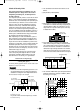
04-396 Inverter-W_a-p50 ARGO 12/21/04 9:38 AM Page 3 2. The standards for minimum room volume are as follows. Check of Density Limit The room in which the air conditioner is to be installed requires a design that in the event of refrigerant gas leaking out, its density will not exceed a set limit. The refrigerant (R410A), which is used in the air conditioner, is safe, without the toxicity or combustibility of ammonia, and is not restricted by laws imposed to protect the ozone layer.
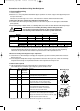
04-396 Inverter-W_a-p50 ARGO 12/21/04 9:38 AM Page 4 Precautions for Installation Using New Refrigerant 1. Care regarding tubing 1-1. Process tubing ● Material: Use C1220 phosphorous deoxidized copper specified in JIS H3300 “Copper and Copper Alloy Seamless Pipes and Tubes.” For tubes of φ19.05 or larger, use C1220 T-1/2H material or H material, and do not bend the tubes. ● Tubing size: Be sure to use the sizes indicated in the table below.
04-396 Inverter-W_a-p50 ARGO 12/21/04 9:38 AM Page 5 3-2. Use R410A exclusive cylinder only. Valve Single-outlet valve (with siphon tube) Liquid refrigerant should be recharged with the cylinder standing on end as shown. Liquid New refrigerant R410A cannot be used for earlier models. 1. Compressor specifications are different. If recharging a R22 or R407C compressor with R410A, durability will significantly decrease since some of the materials used for compressor parts are different. 2.
04-396 Inverter-W_a-p50 ARGO 12/21/04 9:38 AM Page 6 CONTENTS Page Page ■ 4-Way Air Discharge Semi-Concealed Type (ASS Type) . . . . . . . . . . . . . . . . . . . . . . . . . . . .47 3-13. Preparation for Suspending 3-14. Suspending the Indoor Unit 3-15. Placing the Unit Inside the Ceiling 3-16. Installing the Drain Piping 3-17. Checking the Drainage IMPORTANT . . . . . . . . . . . . . . . . . . . . . . . . . . . . . .
04-396 Inverter-W_a-p50 ARGO 12/21/04 9:38 AM Page 7 Page Page 4. HOW TO INSTALL THE OUTDOOR UNIT . . .79 4-1. Transporting 4-2. Installing the Outdoor Unit 10. TEST RUN . . . . . . . . . . . . . . . . . . . . . . . . . . .109 10-1. Preparing for Test Run 10-2. Test Run Procedure 10-3. Main Outdoor Unit PCB Setting 10-4. Sub Outdoor Unit PCB Setting 10-5. Auto Address Setting 10-6. Caution for Pump Down 5. ELECTRICAL WIRING . . . . . . . . . . . . . . . . . . .81 5-1.
04-396 Inverter-W_a-p50 ARGO 12/21/04 9:38 AM Page 8 1. GENERAL CAUTION This booklet briefly outlines where and how to install the air conditioning system. Please read over the entire set of instructions for the indoor and outdoor units and make sure all accessory parts listed are with the system before beginning. 1-1. 1. 2. 3. 4. 5. 6. 7. 8. 9. 10. 11. 12. 13. 14. 15.
04-396 Inverter-W_a-p50 ARGO 12/21/04 9:38 AM Page 9 Table 1-1 (1-Way Air Discharge Semi-Concealed) Part Name Figure Flare insulator Q’ty Remarks 2 For wide and narrow tubes (Black) 3 For wide and narrow tubes (White) 2 For wide and narrow tube flare nuts Vinyl clamp 8 For flare insulator Hose band 1 For securing drain hose Packing 1 For drain joint Drain insulator 1 For drain joint Drain hose 1 For securing drain hose Installation gauge 1 For measuring clearance between th
04-396 Inverter-W_a-p50 ARGO 12/21/04 9:38 AM Page 10 Table 1-3 (2-Way Air Discharge Semi-Concealed) Part Name Figure Flare insulator Q’ty Remarks 2 For wide and narrow tubes 2 For wide and narrow tube flare nuts Vinyl clamp 8 For flare insulator and drain insulator Hose band 1 For securing drain hose Packing 1 For drain joint Drain insulator 1 For drain joint 1 Gauge A (Install on tubing side.) 1 Gauge B (Install on opposite side of tubing.
04-396 Inverter-W_a-p50 ARGO 12/21/04 9:38 AM Page 11 Table 1-6 (Ceiling-Mounted) Part Name Figure Q’ty Special washer T10 Drain insulator Flare insulator Insulating tape T3 T5 Remarks 4 For temporarily suspending indoor unit from ceiling 1 For drain hose joint 2 sets For wide and narrow tube joints White (heat-resisting) 2 For wide and narrow flare joints Vinyl clamp 8 For flare and drain insulator Eyelet 1 For power supply inlet 1 Printed on container box 1 For main unit + PVC
04-396 Inverter-W_a-p50 ARGO 12/21/04 9:38 AM Page 12 Table 1-8 (Concealed-Duct High Static Pressure) Part Name Figure Q’ty Remarks Special washer 8 For suspending indoor unit from ceiling Flare insulator 2 For wide and narrow tubes Drain socket 1 For drain pipe connection Tube connector 1 For increasing size of narrow tube from φ6.35 to φ9.
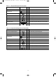
04-396 Inverter-W_a-p50 ARGO 12/21/04 9:38 AM Page 13 1-5. Tubing Size Table 1-11a Main Tubing Size (LA) Unit: mm kW Total system horsepower 16.0 22.4 28.0 33.5 40.0 45.0 50.4 56.0 61.5 68.0 73.0 78.5 85.0 90.0 96.0 6 8 10 12 14 16 18 20 22 24 26 28 30 32 34 Combined outdoor units (6) – – – Wide tubing (mm) ø19.05 ø19.05 ø22.22 Narrow tubing (mm) ø9.52 kW Total system horsepower (8) – (10) – (12) – – – – – – – ø9.
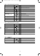
04-396 Inverter-W_a-p50 ARGO 12/21/04 9:38 AM Page 14 Table 1-13 Indoor Unit Tubing Connection ( Indoor unit type Wide tubing (mm) Narrow tubing (mm) 22 28 36 ø12.7 ø6.35 1, 2... 73 56 40) Unit: mm 106 ø15.88 140 280 224 ø19.05 ø22.22 ø9.52 Note: Use C1220T-1/2H material for tubing over φ19.05. 1-6. Straight Equivalent Length of Joints Design the tubing system by referring to the following table for the straight equivalent length of joints.
04-396 Inverter-W_a-p50 ARGO 12/21/04 9:38 AM Page 15 Table 1-17 Refrigerant Charge Amount at Shipment (for outdoor unit) DC (kg) AES06MI2H AES08MI2H AES10MI2H AES12MI2H 7.5 10.0 10.0 10.0 AD (kg) – AES08M2H AES10M2H AES12M2H – 10.0 10.0 10.0 1-8. Combination of Outdoor Units As shown in Table 1-18, a DC unit can be used independently or in combination with an AD unit. ● CAUTION Sub units cannot be used independently.
04-396 Inverter-W_a-p50 ARGO 12/21/04 9:38 AM Page 16 1-10. Tubing Length Select the installation location so that the length and size of refrigerant tubing are within the allowable range shown in the figure below. Main tubing length LM = LA + LB … ≤ 80 m Main distribution tubes LC – LH are selected according to the capacity after the distribution joint. Sizes of indoor unit connection tubing 1 – 40 are determined by the connection tubing sizes on the indoor units. 1. 2.
9:38 AM Page 17 Always check the gas density limit for the room in which the unit is installed. Minimum indoor volume & floor area as against the amount of refrigerant is roughly as given in the following table. 1-11. Check of Limit Density When installing an air conditioner in a room, it is necessary to ensure that even if the refrigerant gas accidentally leaks out, its density does not exceed the limit level for that room. Min. indoor floor area (when the ceiling is 2.
04-396 Inverter-W_a-p50 ARGO 12/21/04 9:38 AM Page 18 1-13. Optional Distribution Joint Kits See the installation instructions packaged with the distribution joint kit for the installation procedure. Table 1-21 Model name Cooling capacity after distribution Remarks 1. DDVE68 68.0 kW or less For outdoor unit 2. DDVE135 135.0 kW or less For outdoor unit 3. DDVI16 22.4 kW or less For indoor unit 4. DDVI68 68.0 kW or less For indoor unit 5. DDVI135 135.0 kW or less For indoor unit 1.
04-396 Inverter-W_a-p50 ARGO 12/21/04 9:38 AM Page 19 3. DDVI16 Use: For indoor unit (Capacity after distribution joint is 22.4 kW or less.) Example: (F below indicates inner diameter. F below indicates outer diameter.) Wide tube 55 210 Narrow tube 185 50 F F 145 103 HG H H J H H F GH J 83 F F F H G H J 135 Insulator Insulator 4. DDVI68 Use: For indoor unit (Capacity after distribution joint is greater than 22.4 kW and no more than 68.0 kW.) Example: (F below indicates inner diameter.
04-396 Inverter-W_a-p50 ARGO 12/21/04 9:38 AM Page 20 1-14. Optional Ball Valve Kits Table 1-26 Valve connecting tube size (mm) Model No. Indoor unit where used Wide tube Narrow tube Balance valve Outdoor unit where used Total capacity of indoor units after the valve BV-RXP335AG 25.4 12.7 – 12 hp More than 30.0 kW and less than 42.0 kW BV-RXP280AG 22.22 9.52 – 10 hp Less than 30.0 kW BV-RXP224AG 19.05 9.52 – 6, 8 hp 22.4 kW or less BV-RXP160AG 15.88 9.52 – – 16.
04-396 Inverter-W_a-p50 ARGO 12/21/04 9:38 AM Page 21 Ball Valve Installation (for refrigerant R410A only) Check the size of the ball valve set you separately purchased. Model name Size BV-RXP56AG φ6.35 • φ12.7 BV-RXP160AG φ9.52 • φ15.88 BV-RXP224AG φ9.52 • φ19.05 BV-RXP280AG φ9.52 • φ22.22 BV-RXP335AG φ12.7 • φ25.4 Valves with φ19.05, φ22.22, or φ25.4 connections are brazing type. All others are flare-nut type. 1.
04-396 Inverter-W_a-p50 ARGO 12/21/04 9:38 AM Page 22 3. Opening and closing the valve This valve is open at the time of shipment from the factory. If the valve is used for extension, be sure to close it. Valve opened Valve closed Spindle Spindle 4. Installing thermal insulation The thermal insulation used for a flare-nut type valve is in the form of a bag. When the valve is used for extension, it can be used as-is.
04-396 Inverter-W_a-p50 ARGO 12/21/04 9:38 AM Page 23 1-15. Recommended Location of Ball Valves ● It is recommended that a ball valve kit be installed for each outdoor unit. ● Select a valve location that allows service to be easily provided for each unit or each refrigerant system. (1) When adding ball valve for indoor unit 1. Location: Install the ball valve at the distribution tube (not main tube).
04-396 Inverter-W_a-p50 ARGO 12/21/04 9:38 AM Page 24 1-16. Example of Tubing Size Selection and Refrigerant Charge Amount Additional refrigerant charging Based on the values in Tables 1-11a, 11b, 12, 13 and 16, use the narrow tubing size and length, and calculate the amount of additional refrigerant charge using the formula below. Required additional –3 refrigerant charge (kg) = [366 × (a) + 259 × (b) + 185 × (c) + 128 × (d) + 56 × (e) + 26 × (f)] × 10 (a) : Narrow tubing Total length of φ22.
04-396 Inverter-W_a-p50 ARGO ● 12/21/04 9:38 AM Page 25 Obtain narrow tubing size from Tables 1-11a, 11b, 12, 13 and 16. Main tubing LO = φ15.88 m (Total capacity of outdoor unit is 50.4 kW) LA = φ19.05 m (Total capacity of indoor unit is 88.4 kW) LB = φ19.05 m (Total capacity of indoor unit is 77.2 kW) LC = φ15.88 m (Total capacity of indoor unit is 66.0 kW) LD = φ15.88 m (Total capacity of indoor unit is 52.0 kW) LE = φ12.7 m (Total capacity of indoor unit is 38.0 kW) LF = φ9.
04-396 Inverter-W_a-p50 ARGO 12/21/04 9:38 AM Page 26 Ceiling-Mounted Type 2. SELECTING THE INSTALLATION SITE Ceiling 2-1. Indoor Unit Wall AVOID: ● areas where leakage of flammable gas may be expected. ● places where large amounts of oil mist exist. ● direct sunlight. ● locations near heat sources which may affect the performance of the unit. min. 25 cm Front view min. 25 cm NOTE ● Air discharge locations where external air may enter the room directly.
04-396 Inverter-W_a-p50 ARGO 12/21/04 9:38 AM Page 27 2-2. Outdoor Unit Exhaust fan AVOID: Hot air ● heat sources, exhaust fans, etc. ● damp, humid or uneven locations ● indoors (no-ventilation location) Heat source Outdoor unit DO: ● choose a place as cool as possible. ● choose a place that is well ventilated. ● allow enough room around the unit for air intake/ exhaust and possible maintenance. Fig.
04-396 Inverter-W_a-p50 ARGO 12/21/04 9:38 AM Page 28 2-3. Shield for Horizontal Exhaust Discharge It is necessary to install an air-discharge chamber (field supply) to direct exhaust from the fan horizontally if it is difficult to provide a minimum space of 2 m between the air-discharge outlet and a nearby obstacle. (Fig. 2-9) CAUTION In regions with heavy snowfall, the outdoor unit should be provided with a solid, raised platform and snowproof vents. (Fig. 2-10) 2-4.
04-396 Inverter-W_a-p50 ARGO 12/21/04 9:38 AM Page 29 2-6. Dimensions of Wind Ducting Reference diagram for air-discharge chamber (field supply) - 1 08 / 10 / 12 unit Air direction: Front direction example Unit: mm Note: Can be installed so that the air direction is to the front or rear direction. 06 unit Air direction: Front direction example Unit: mm Note: Can be installed so that the air direction is to the front or rear direction.
04-396 Inverter-W_a-p50 ARGO 12/21/04 9:38 AM Page 30 Reference diagram for air-discharge chamber (field supply) - 2 08 / 10 / 12 unit Unit: mm 06 unit Unit: mm 30
04-396 Inverter-W_a-p50 ARGO 12/21/04 9:38 AM Page 31 2-7. Dimensions of Snow Ducting Reference diagram for snow-proof vents (field supply) - 1 08 / 10 / 12 unit Air direction: Front direction example Unit: mm Note: Can be installed so that the air direction is to the front or rear direction. 06 unit Air direction: Front direction example Unit: mm Note: Can be installed so that the air direction is to the front or rear direction.
04-396 Inverter-W_a-p50 ARGO 12/21/04 9:38 AM Page 32 Reference diagram for snow-proof vents (field supply) - 2 1 2 3 4 Part name Air direction chamber Air intake duct Air intake duct (front) Spacer Model No.
04-396 Inverter-W_a-p50 ARGO 12/21/04 9:38 AM Page 33 3. HOW TO INSTALL THE INDOOR UNIT ■ 1-Way Air Discharge Semi-Concealed Type (AS1S Type) Unit: mm 780 (Ceiling opening dimension) AS1S Insert suspension bolts as shown in Fig. 3-3 or 74 4 – 12 × 37 oblong holes Use existing ceiling supports or construct a suitable support as shown in Fig. 3-4. Drain outlet Unit: mm 560 268 Suspension lug 20 15 Power wiring outlet 65 15 (3) Cut the ceiling material, if necessary. (Figs.
04-396 Inverter-W_a-p50 ARGO 12/21/04 9:38 AM Page 34 If the system requires fresh air to be drawn into the unit, cut and remove the insulation (both externally and internally) at the location shown as A in Fig. 3-5. CAUTION Unit: mm When making the cuts to the insulation, be careful not to damage the drain pan. 140 AS1S 177 For fresh air intake (ø125 hole) A 3-2. Placing the Unit Inside the Ceiling Fig.
04-396 Inverter-W_a-p50 ARGO 12/21/04 9:38 AM Page 35 (4) Adjust the distance between the unit and the opening in the ceiling to give clearances of 15 mm in the front and back directions and 70 mm in the right and left directions so that the height between the bottom surface of the flange of the unit and the bottom surface of the ceiling is 37 mm, and the air-intake side is 5 mm. To check these dimensions for positioning the unit, use the installation gauge which is taped on the unit. (Fig.
04-396 Inverter-W_a-p50 ARGO 12/21/04 9:38 AM Page 36 CAUTION Air bleeder AS1S ● Do not install an air bleeder as this may cause water to spray from the drain pipe outlet. (Fig. 3-12) ● If it is necessary to increase the height of the drain pipe, the section directly after the connection port can be raised a maximum of 50 cm. Do not raise it any higher than 50 cm, as this could result in water leaks. (Fig. 3-13) ● Do not install the pipe with an upward gradient from the connection port.
04-396 Inverter-W_a-p50 ARGO 12/21/04 9:38 AM Page 37 3-4. Checking the Drainage After wiring and drain piping are completed, use the following procedure to check that the water will drain smoothly. For this, prepare a bucket and wiping cloth to catch and wipe up spilled water. (1) Connect power to the power terminal board (R, S terminals) inside the electrical component box. Drain pan (2) Pour water into the drain pan about 500 cc using a siphon pump through the air outlet grille. (Fig. 3-16) Fig.
04-396 Inverter-W_a-p50 ARGO 12/21/04 9:38 AM Page 38 ■ 1-Way Air Discharge Semi-Concealed Slim Type (ASBS Type) Front face 3-5. Suspending the Indoor Unit (1) Place the full-scale diagram (supplied) on the ceiling at the spot where you want to install the indoor unit. Use a pencil to mark the drill holes. Refer to Table 3-1 and Figs. 3-17 and 3-19. Rear Full-scale diagram ASBS Fig.
12/21/04 9:38 AM Page 39 (5) If the system requires fresh air to be drawn into the unit, cut and remove the insulation (both externally and internally) at the location shown as A in Fig. 3-22. Unit: mm 88 125 635 88 04-396 Inverter-W_a-p50 ARGO 3-6. Placing the Unit Inside the Ceiling Fresh air intake knock-out hole ø125 (1) When placing the unit inside the ceiling, determine the pitch of the suspension bolts using the supplied full-scale installation diagram. (Fig.
04-396 Inverter-W_a-p50 ARGO 12/21/04 9:38 AM Page 40 3-7. Installing the Drain Piping (1) Prepare standard hard PVC pipe (O.D. 32 mm) for the drain and use the supplied drain hose and hose band to prevent water leaks. The PVC pipe must be purchased separately. The unit’s transparent drain port allows you to check drainage. (Fig. 3-26a) ASBS Align the hose band with end of the hose, and tighten so that it does not contact the bead.
04-396 Inverter-W_a-p50 ARGO 12/21/04 9:38 AM Page 41 Air bleeder prohibited CAUTION ● ● ● ● ● Do not install an air bleeder as this may cause water to spray from the drain pipe outlet. (Fig. 3-27) Fig. 3-27 If it is necessary to increase the height of the drain pipe, the pipe can be raised a maximum of 59 cm from the bottom of the ceiling. Do not raise it any higher than 59 cm, as this could result in water leaks. (Fig.
04-396 Inverter-W_a-p50 ARGO 12/21/04 9:38 AM Page 42 (4) When the check of drainage is complete, open the check pin (CHK) and remount the insulator. CAUTION ASBS Use 4 × 8 tapping screws to fasten cover drainage. If the screws used are longer than 8 mm, it may make a hole in the drain pan and cause leakage. Drain pump installation screw Cleaning the sub drain pan Before beginning work, make necessary preparations (e.g., prepare a bucket, wiping cloth, etc.).
9:38 AM Page 43 530 Suspension bolt pitch ■ 2-Way Air Discharge Semi-Concealed Type (AS2S Type) (1) Follow the diagrams to make the holes in the ceiling. Table 3-2 600 3-9.
04-396 Inverter-W_a-p50 ARGO 12/21/04 9:38 AM Page 44 2 CAUTION ø 16 (5) If the system requires fresh air to be drawn into the unit, cut and remove the insulation (both externally and internally) at the location shown as A in Fig. 3-38. 50 ø1 ø1 38 When making the cuts to the insulation, be careful not to damage the drain pan. A 3-10. Placing the Unit Inside the Ceiling Fig. 3-38 (1) When placing the unit inside the ceiling, determine the pitch of the suspension bolts.
04-396 Inverter-W_a-p50 ARGO 12/21/04 9:38 AM Page 45 (2) After checking the drainage, wrap the supplied packing and drain pipe insulator around the pipe, then secure it with the supplied clamps. (Fig. 3-42) Drain insulator (supplied) NOTE Make sure the drain pipe has a downward gradient (1/100 or more) and that there are no water traps. Vinyl clamps Fig. 3-42 CAUTION Air bleeder prohibited ● Do not install an air bleeder as this may cause water to spray from the drain pipe outlet. (Fig.
04-396 Inverter-W_a-p50 ARGO 12/21/04 9:38 AM Page 46 3-12. Checking the Drainage After wiring and drain piping are completed, use the following procedure to check that the water will drain smoothly. For this, prepare a bucket and wiping cloth to catch and wipe up spilled water. (1) Connect power to the power terminal board (R, S terminals) inside the electrical component box. (2) Remove the tube cover and through the opening, slowly pour about 1,200 cc of water into the drain pan to check the drainage.
04-396 Inverter-W_a-p50 ARGO 12/21/04 9:38 AM Page 47 ■ 4-Way Air Discharge Semi-Concealed Type (ASS Type) Note: For DC Fan Tap Change Procedure for 4-Way Cassette, see page 139. 3-13. Preparation for Suspending This unit uses a drain pump. Use a carpenter’s level to check that the unit is level. Hole-in-anchor Hole-in-plug 3-14. Suspending the Indoor Unit (1) Fix the suspension bolts securely in the ceiling using the method shown in the diagrams (Figs.
04-396 Inverter-W_a-p50 ARGO 12/21/04 9:38 AM Page 48 3-15. Placing the Unit Inside the Ceiling (1) When placing the unit inside the ceiling, determine the pitch of the suspension bolts using the supplied full-scale installation diagram. (Fig. 3-51) (2) The length of suspension bolts must be appropriate for a distance between the bottom of the bolt and the bottom of the unit of more than 15 mm as shown in Fig. 3-51.
04-396 Inverter-W_a-p50 ARGO 12/21/04 9:38 AM Page 49 3-16. Installing the Drain Piping (1) Prepare a standard hard PVC pipe (O.D. 32 mm) for the drain and use the supplied drain hose and hose band to prevent water leaks. The PVC pipe must be purchased separately. The unit’s transparent drain port allows you to check drainage. (Fig.
04-396 Inverter-W_a-p50 ARGO 12/21/04 ● CAUTION ● ASS ● ● 9:38 AM Page 50 If it is necessary to increase the height of the drain pipe, the section directly after the connection port can be raised a maximum of 64 cm. Do not raise it any higher than 64 cm, as this could result in water leaks. (Fig. 3-56) 30 cm or less (as short as possible) 64 cm or less Fig. 3-56 Do not install the pipe with an upward gradient from the connection port.
04-396 InverterW_p51-108 ARGO 12/21/04 10:17 AM Page 51 ■ Wall-Mounted Type (AWS Type) 3-18. Removing the Rear Panel from the Unit (1) Remove the set screws used to fasten the rear panel to the indoor unit during transportation. (2) Press up on the frame at the 2 locations shown by the arrows in the figure at right, and remove the rear panel. Screws used during transportation Press NOTE Remove the rear panel Tubing can be extended in 4 directions as shown in Fig. 3-61.
04-396 InverterW_p51-108 ARGO 12/21/04 10:17 AM Page 52 3-20. Installing the Rear Panel onto the Wall Confirm that the wall is strong enough to support the unit. See either Item a) or b) below depending on the wall type. a) If the Wall is Wooden (1) Attach the rear panel to the wall with the 10 screws provided. (Fig.
04-396 InverterW_p51-108 ARGO 12/21/04 10:17 AM Page 53 3-22. Preparing the Tubing Frame (1) Arrangement of tubing by directions a) Right or left tubing Right tubing outlet The corner of the right or left frame should be cut with a hack saw or similar. (Fig. 3-72) b) Right-rear or left-rear tubing When left and right side tubing In this case, the corners of the frame do not need to be cut. Fig.
04-396 InverterW_p51-108 ARGO 12/21/04 10:17 AM Page 54 Left or left-rear tubing (1) Pass the tubing and drain hose into the rear of the indoor unit. Provide sufficient length for the connections to be made. Next, bend the tubing with a pipe bender, and connect them. Insulation Fig. 3-77 (2) After performing a leak test, wrap the refrigerant tubing and drain hose together with insulating tape, as shown in the figure at right.
04-396 InverterW_p51-108 ARGO 12/21/04 10:17 AM Page 55 ■ Ceiling Mounted Type (ACS Type) 3-25. Required Minimum Space for Installation and Service (1) Dimensions of suspension bolt pitch and unit 36, 56 855 910 210 73 1125 1180 210 106, 140 1540 1595 210 Unit: mm Air intake 680 C C 170 B 320 A Type B (Suspension bolt pitch) Length Ceiling side A 27.5 Air 27.5 (Suspension bolt pitch) Fig.
04-396 InverterW_p51-108 ARGO 12/21/04 10:17 AM Page 56 (4) Wall and ceiling side opening position 145 Ceiling 90 90 Figure shows view from top * Wall 155 Figure shows view from front φ100 ceiling opening φ100 wall side opening 135 φ100 wall side opening (for left-side drain hose) φ100 ceiling opening 125 Unit: mm * If the optional drain up kit is installed, create a φ100 hole along the dotted line (part marked with * in figure). Fig. 3-83 3-26.
04-396 InverterW_p51-108 ARGO 12/21/04 10:17 AM Page 57 (5) Before suspending the indoor unit, remove the 2 or 3 screws on the latch of the air-intake grilles, open the grilles, and remove them by pushing the claws of the hinges as shown in Fig. 3-88a. Then remove both side panels sliding them along the unit toward the front after removing the 2 attachment screws. (Fig.
04-396 InverterW_p51-108 ARGO 12/21/04 10:17 AM Page 58 b) Lift the indoor unit, and place it on the washers through the notches, in order to fix it in place. (Fig. 3-90) c) Tighten the 2 hexagonal nuts on each suspension bolt to suspend the indoor unit as shown in Fig. 3-91. NOTE The ceiling surface is not always level. Please confirm that the indoor unit is evenly suspended.
04-396 InverterW_p51-108 ARGO 12/21/04 10:17 AM Page 59 3-27. Duct for Fresh Air Rear outlet port There is a duct connection port (knock-out hole) at the right-rear of the top panel of the indoor unit for drawing in fresh air. If it is necessary to draw in fresh air, remove the cover by opening the hole and connecting the duct to the indoor unit through the connection port. (Fig.
04-396 InverterW_p51-108 ARGO ● 12/21/04 10:17 AM Page 60 If other commercially available hose bands are used, the drain hose may become pinched or wrinkled and there is danger of water leakage. Therefore be sure to use the supplied hose bands. When sliding the hose bands, be careful to avoid scratching the drain hose. ● Do not use adhesive when connecting the supplied drain hose to the drain port (either on the main unit or the PVC pipe).
04-396 InverterW_p51-108 ARGO 12/21/04 10:17 AM Page 61 How to carry out power supply wiring (1) Wiring connection ports The power inlet ports are located at the rear and top. The remote controller wiring inlet ports are located at the rear and top (for use with the wired remote controller). For details, refer to Fig. 3-94a on page 58. For the method used to insert the wiring, refer to the figure below. (Fig.
04-396 InverterW_p51-108 ARGO 12/21/04 10:17 AM Page 62 3-30. Required Minimum Space for Installation and Service ● ● min. 250 Electrical component box Inspection access 450 450 Indoor unit The minimum space for installation and service is shown in Fig. 3-98 and Table 3-5. It is recommended that space is provided (450 × 450 mm) for checking and servicing the electrical system. Air outlet duct flange Type min. 650 Unit: mm Fig.
04-396 InverterW_p51-108 ARGO 12/21/04 10:17 AM Page 63 3-31. Suspending the Indoor Unit Depending on the ceiling type: • Insert suspension bolts as shown in Fig. 3-100 or Hole-in-anchor Hole-in-plug • Use existing ceiling supports or construct a suitable support as shown in Fig. 3-101. WARNING It is important that you use extreme care in supporting the indoor unit inside the ceiling. Ensure that the ceiling is strong enough to support the weight of the unit.
04-396 InverterW_p51-108 ARGO ● 12/21/04 10:17 AM Page 64 Fig. 3-104 shows an example of installation. Bolt anchor Air outlet duct Suspension bolt Air-intake duct Air-outlet grille Ceiling material Indoor unit Air-intake grille Fig. 3-104 3-32. Installing the Drain Piping (1) Prepare standard hard PVC pipe (O.D. 32 mm) for the drain and use the supplied hose band to prevent water leaks. The PVC pipe must be purchased separately. The transparent drain part on the unit allows you to check drainage.
04-396 InverterW_p51-108 ARGO 12/21/04 ● CAUTION 10:17 AM Page 65 Do not install an air bleeder as this may cause water to spray from the drain pipe outlet. (Fig. 3-106) Air bleeder Prohibited ● ● ● If it is necessary to increase the height of the drain pipe, the section directly after the connection port can be raised a maximum of 50 cm. Do not raise it any higher than 50 cm, as this could result in water leaks. (Fig. 3-107) Fig.
10:17 AM Page 66 3-34. Increasing the Fan Speed Electrical component box If external static pressure is too great (due to long extension of ducts, for example), the air flow volume may drop too low at each air outlet. This problem may be solved by increasing the fan speed using the following procedure: Booster cable Fan motor Booster cable Fan motor socket (At shipment) (1) Remove 4 screws on the electrical component box and remove the cover plate. (Booster cable installed) Fig.
04-396 InverterW_p51-108 ARGO 12/21/04 10:17 AM Page 67 ■ Concealed-Duct High Static Pressure Type (ADPS Type) (mm) 130 3-35. Required Minimum Space for Installation and Service (73, 106, 140 Type) ● The minimum space for installation and service is shown in Fig. 3-113a. ● It is recommended that space be provided (600 × 600 mm) for checking and servicing the electrical system.
12/21/04 10:17 AM Page 68 3-36. Required Minimum Space for Installation and Service (224, 280 Type) ● This air conditioner is usually installed above the ceiling so that the indoor unit and ducts are not visible. Only the air intake and air outlet ports are visible from below. The minimum space for installation and service is shown in Fig. 3-114a. ● It is recommended that space be provided (600 × 600 mm) for checking and servicing the electrical system. Air suction side (mm) 55 ● ● 1170 Min.
04-396 InverterW_p51-108 ARGO 12/21/04 10:17 AM Page 69 3-37. Suspending the Indoor Unit Hole-in-anchor Hole-in-plug Depending on the ceiling type: ● Concrete Insert Insert suspension bolts as shown in Fig. 3-115 or ● Use existing ceiling supports or construct a suitable support as shown in Fig. 3-116. Suspension bolt (M10 or 3/8") (field supply) It is important that you use extreme care in supporting the indoor unit inside the ceiling.
04-396 InverterW_p51-108 ARGO 12/21/04 10:17 AM Page 70 3-38. Installing the Refrigerant Tubing The size of the refrigerant tubing is as shown in the table below. Table 3-8 ● 224 Type 280 Type Wide tube (mm) φ19.05 (Brazing connection) φ22.22 (Brazing connection) Narrow tube (mm) φ9.52 (Flare connection) φ9.
04-396 InverterW_p51-108 ARGO 12/21/04 10:17 AM Page 71 Air-outlet grille Air-intake grille Fig. 3-119 3-39. Installing the Drain Piping (1) Prepare standard hard PVC pipe (O.D. 32 mm) for the drain and use the supplied drain socket to prevent water leaks. The PVC pipe must be purchased separately. When doing this, apply adhesive for the PVC pipe at the connection point.
04-396 InverterW_p51-108 ARGO 12/21/04 10:17 AM Page 72 3-40. Caution for Ducting Work ● This unit has high static pressure (applicable external static pressure Max. 167 to 216 pa (17–22 mm Aq). In the case of small pressure resistance (for instance, a short duct), install a damper for adjusting air flow volume as air flow volume / air flow noise increases.
04-396 InverterW_p51-108 ARGO 12/21/04 10:17 AM Page 73 3-41. Increasing the Fan Speed (280 Type only) If external static pressure is too great (due to long extension of ducts, for example), the air flow volume may drop too low at each air outlet. This problem may be solved by increasing the fan speed using the following procedure: Electrical component box (1) Remove 4 screws on the electrical component box and remove the cover plate.
04-396 InverterW_p51-108 ARGO 12/21/04 10:17 AM Page 74 ■ Floor-Standing Type (AFS Type) Concealed Floor-Standing Type (AFNS Type) 3-42. Required Minimum Space for Installation and Service Horizontal view min. 10 cm Install the unit where cooled or heated air from the unit can circulate well in the room. Do not put obstacles which may obstruct the air flow in front of the air intake and outlet grilles. Vertical view min. 10 cm min. 100 cm min. 100 cm NOTE Fig.
04-396 InverterW_p51-108 ARGO 12/21/04 10:17 AM Page 75 Concealed Floor-Standing Type (AFNS Type) 1 4-ø12 holes (for fastening the indoor unit to the floor with screws) 2 Air filter 3 Refrigerant connection outlet (narrow tube) 4 Refrigerant connection outlet (wide tube) 5 Level adjusting bolt 6 Drain outlet (20A) 7 Flange for air-outlet duct Table 3-10 Type Unit: mm Length A B C D Narrow tube Wide tube 22, 28, 36 858 692 672 665 9.52 12.7 56, 73 1173 1007 1002 980 9.52 15.
04-396 InverterW_p51-108 ARGO 12/21/04 10:17 AM Page 76 3-44. Removing and Attaching the Front Panel (Floor-Standing Type) NOTE A dew-prevention heater is secured behind the front panel. When removing or attaching the panel, take care not to damage the lead wire to the heater. How to remove the front panel A (1) Remove the 2 screws at the lower part of the front panel. (2) Holding A at the upper right of the unit, push up at B at the lower right of the panel.
04-396 InverterW_p51-108 ARGO CAUTION ● 12/21/04 10:17 AM Page 77 Insulate both wide and narrow tubes. To insulate tubes (1) Wrap the flare nuts with the supplied white insulating tape. (2) Wrap the flare nuts with the supplied flare insulator. (3) Fill the clearance between the union insulator and flare insulator with black insulating tape. Fasten both ends of the flare insulator with the supplied vinyl clamps.
04-396 InverterW_p51-108 ARGO 12/21/04 10:17 AM Page 78 3-46. Installing the Drain Piping Water leaks may occur if the drain pipes are connected inadequately. CAUTION (1) When rear-side drain piping is required bend the drain hose attached to the indoor unit by 90°. Connect a drain pipe (field supply) to the drain hose through the rear tubing outlet in the rear panel. Use a hard PVC pipe (VP20) for the drain piping.
04-396 InverterW_p51-108 ARGO 12/21/04 10:17 AM Page 79 4. HOW TO INSTALL THE OUTDOOR UNIT Rope Fan guard 4-1. Transporting 70˚ When transporting the unit, have it delivered as close to the installation site as possible without unpacking. Supplied cardboard strips Use a hook for suspending the unit. (Fig. 4-1) CAUTION ● ● When hoisting the unit, pass the lifting ropes under the bottom plate as shown in the figure at right.
04-396 InverterW_p51-108 ARGO 12/21/04 10:17 AM Page 80 Installation examples 125 125 830 890 125 90 925 925 925 925 90 90 Unit: mm Fig. 4-5 925 890 830 125 783 90 Fig.
04-396 InverterW_p51-108 ARGO 12/21/04 10:17 AM Page 81 5. ELECTRICAL WIRING 5-1. General Precautions on Wiring (1) Before wiring, confirm the rated voltage of the unit as shown on its nameplate, then carry out the wiring closely following the wiring diagram. (7) Regulations on wire diameters differ from locality to locality. For field wiring rules, please refer to your LOCAL ELECTRICAL CODES before beginning.
04-396 InverterW_p51-108 ARGO 12/21/04 10:17 AM Page 82 5-3. Wiring System Diagrams Indoor unit (No. 1) L Power supply 220-240V 50Hz N 1 2 Ground Remote controller WHT 1 BLK 2 Outdoor unit INV unit C B U2 D Ground R1 1 2 3 4 R2 A L1 L2 L3 N 1 2 3 4 5 U1 U2 U1 Power supply 380-415V-3N 50 Power supply 380-415V-3N 50 Ground Ground C Indoor unit (No.
04-396 InverterW_p51-108 ARGO 12/21/04 10:17 AM Page 83 CAUTION (1) When linking outdoor units in a network (S-net link system), disconnect the terminal extended from the short plug (CN003, 2P Black, location: right bottom on the outdoor main control PCB) from all outdoor units except any one of the outdoor units. (When shipping: In shorted condition.) Otherwise the communication of S-net link system is not performed.
04-396 InverterW_p51-108 ARGO 12/21/04 10:17 AM Page 84 (5) Use shielded wires for inter-unit control wiring (c) and ground the shield on both sides, otherwise misoperation from noise may occur. (Fig. 5-4) Connect wiring as shown in Section “5-3. Wiring System Diagrams.” WARNING Shielded wire Ground Loose wiring may cause the terminal to overheat or result in unit malfunction. A fire hazard may also exist. Therefore, ensure that all wiring is tightly connected. Ground Fig.
12/21/04 10:17 AM Page 85 6. HOW TO INSTALL THE REMOTE CONTROLLER (OPTIONAL PART) CAUTION Remote controller wiring can be extended to a maximum of 1,000 m. ■ How to install the remote controller (Optional Controller) ● CAUTION Opening for switch box M4 × 25 screws (2) Do not twist the control wiring with the power wiring or run it in the same metal conduit, because this may cause malfunction. ● Install the remote controller away from sources of electrical noise.
04-396 InverterW_p51-108 ARGO 12/21/04 10:17 AM Page 86 6-2. Basic Wiring Diagram CAUTION ● Install wiring correctly (incorrect wiring will damage the equipment). Remote control wiring Standard Group control Connection wiring remote control Multiple remote control for group control Use shielded wires for remote control wiring and ground the shield on both sides. (Fig. 6-3) Otherwise misoperation due to noise may occur. 1 2 Terminal 3P 1 2 1 2 Indoor unit No. 2 1 2 Indoor unit No.
04-396 InverterW_p51-108 ARGO 12/21/04 10:17 AM Page 87 Setting the main and sub remote controllers 1. Set one of the 2 connected remote controllers as the main remote controller. 2. On the other remote controller (sub-remote controller), switch the remote controller address connector on the rear of the remote controller PCB from Main to Sub. When the connector has been switched, the remote controller will function as the sub-remote controller.
04-396 InverterW_p51-108 ARGO 12/21/04 10:17 AM Page 88 6-4. Switching the Room Temperature Sensors Room temperature sensors are contained in the indoor unit and in the remote controller. One or the other of the temperature sensors is used for operation. Normally, the indoor unit sensor is set; however, the procedure below can be used to switch to the remote controller sensor. (1) Press and hold the + + buttons for 4 seconds or longer. NOTE ● The unit No.
04-396 InverterW_p51-108 ARGO 12/21/04 10:17 AM Page 89 6-6. Wiring the Remote Controller ● Connection diagram Approx. 200 mm Terminal board for indoor unit remote controller wiring W BK 1 2 Connector Remote controller wiring (field supply) 1 2 Remote controller unit Power wire from remote controller unit ● Use 0.5 mm2 – 2 mm2 wires. (1) Strip the insulation to approximately 14 mm from the ends of the wires that will be connected.
04-396 InverterW_p51-108 ARGO 12/21/04 10:17 AM Page 90 6-7. Meanings of Alarm Messages Table of Self-Diagnostics Functions and Description of Alarm Displays. Alarm messages are indicated by the blinking of LED 1 and 2 (D72, D75) on the outdoor unit PCB. They are also displayed on the wired remote controller. ● Viewing the LED 1 and 2 (D72 and D75) alarm displays LED 1 LED 2 Alternating ( Alarm contents Alarm display LED 1 blinks M times, then LED 2 blinks N times. The cycle then repeats.
04-396 InverterW_p51-108 ARGO 12/21/04 10:17 AM Page 91 Alarm message Possible cause of malfunction Activation of protective device Protective device in outdoor unit is activated. Compressor thermal protector is activated. Power supply voltage is unusual. (The voltage is more than 260 V or less than 160 V between L and N phase.) Incorrect discharge temperature. (Comp. No. 1) High pressure switch is activated. Negative (Defective) phase. Incorrect discharge temperature. (Comp. No.
04-396 InverterW_p51-108 ARGO 12/21/04 10:17 AM Page 92 Alarm messages displayed on system controller Serial communication errors Mis-setting Activation of protective device Error in transmitting serial communication signal Indoor or main outdoor unit is not operating correctly. Mis-wiring of control wiring between indoor unit, main outdoor unit and system controller. C05 Error in receiving serial communication signal Indoor or main outdoor unit is not operating correctly.
04-396 InverterW_p51-108 ARGO 12/21/04 10:17 AM Page 93 7. HOW TO PROCESS TUBING Deburring The narrow tubing side is connected by a flare nut, and the wide tubing side is connected by brazing. After Before 7-1. Connecting the Refrigerant Tubing Use of the Flaring Method Many of conventional split system air conditioners employ the flaring method to connect refrigerant tubes which run between indoor and outdoor units.
04-396 InverterW_p51-108 ARGO 12/21/04 10:17 AM Page 94 Caution Before Connecting Tubes Tightly (1) Apply a sealing cap or water-proof tape to prevent dust or water from entering the tubes before they are used. Apply refrigerant lubricant here and here (2) Be sure to apply refrigerant lubricant to the matching surfaces of the flare and union before connecting them together. This is effective for reducing gas leaks. (Fig. 7-4) Fig.
04-396 InverterW_p51-108 ARGO 12/21/04 10:17 AM Page 95 7-3. Insulating the Refrigerant Tubing Two tubes arranged together Tubing Insulation ● Narrow tubing Thermal insulation must be applied to all unit tubing, including distribution joint (purchased separately). * For gas tubing, the insulation material must be heat resistant to 120°C or above. For other tubing, it must be heat resistant to 80°C or above. Insulation material thickness must be 10 mm or greater.
04-396 InverterW_p51-108 ARGO 12/21/04 10:17 AM Page 96 7-4. Taping the Tubes (1) At this time, the refrigerant tubes (and electrical wiring if local codes permit) should be taped together with armoring tape in 1 bundle. To prevent the condensation from overflowing the drain pan, keep the drain hose separate from the refrigerant tubing. Clamp (2) Wrap the armoring tape from the bottom of the outdoor unit to the top of the tubing where it enters the wall.
04-396 InverterW_p51-108 ARGO 12/21/04 10:17 AM Page 97 8. AIR PURGING Manifold gauge Air and moisture in the refrigerant system may have undesirable effects as indicated below. ● ● ● ● ● pressure in the system rises operating current rises cooling (or heating) efficiency drops moisture in the refrigerant circuit may freeze and block capillary tubing water may lead to corrosion of parts in the refrigerant system Fig.
04-396 InverterW_p51-108 ARGO 12/21/04 10:17 AM Page 98 (4) Do a leak test of all joints of the tubing (both indoor and outdoor) and both wide and narrow service valves. Bubbles indicate a leak. Wipe off the soap with a clean cloth after a leak test. Manifold valve (5) After the system is found to be free of leaks, relieve the nitrogen pressure by loosening the charge hose connector at the nitrogen cylinder. When the system pressure is reduced to normal, disconnect the hose from the cylinder.
04-396 InverterW_p51-108 ARGO 12/21/04 10:17 AM Page 99 Manifold valve NOTE The required time in the above table is calculated based on the assumption that the ideal (or target) vacuum condition is less than 667 Pa (–755 mm Hg, 5 Torr). Pressure gauge Lo Hi Valve (2) When the desired vacuum is reached, close the “Lo” knob of the manifold valve and turn off the vacuum pump. Please confirm that the gauge pressure is under 667 Pa (–755 mmHg, 5 Torr) after 4 to 5 minutes of vacuum pump operation.
04-396 InverterW_p51-108 ARGO 12/21/04 10:17 AM Page 100 9. HOW TO INSTALL THE CEILING PANEL ■ 1-Way Air Dischange Semi-Concealed Type (AS1S Type) 9-1. Installing the Ceiling Panel (1) Screw the M5 × 40 screws supplied (in the unit packing) into 4 points on the flange surface of the unit bolted to the ceiling. Insert the screws so that the distance between the bottom of the screw head and the bottom surface of the flange is at least 19.05 mm. (Fig.
04-396 InverterW_p51-108 ARGO 12/21/04 10:17 AM Page 101 ■ 1-Way Air Discharge Semi-Concealed Slim Type (ASBS Type) 9-3. Installing the Ceiling Panel (1) Hook the 2 panel catches of the ceiling panel to the tubing side (stationary side) of the indoor unit. Then, press up on the opposite side to engage the level catch to install by opening the level catch (pressed with fingers.) (Fig. 9-2) Make sure the ceiling panel is mounted correctly.
04-396 InverterW_p51-108 ARGO 12/21/04 10:17 AM Page 102 (4) Check to see that the ceiling panel is properly aligned with the seamline of the ceiling. If not, readjust the indoor unit by adjusting the nuts to the proper suspension point. (Fig. 9-4) Suspension bolt (5) For attaching and removing the side panels, see Fig. 9-5. ● ASBS ● Nut, washer Attaching the side panels Put the center claw of the side panel into the center recess of the indoor unit.
04-396 InverterW_p51-108 ARGO 12/21/04 10:17 AM Page 103 ■ 2-Way Air Discharge Semi-Concealed Type (AS2S Type) Indoor unit Ceiling Unit: mm (2) Remove the air-intake panel and the air filter from the ceiling panel as shown in Figs. 9-7 and 9-8. CAUTION Never touch or attempt to move the air-direction louver by hand or you may damage the unit. Instead, use the remote controller if you want to change the direction of air flow.
04-396 InverterW_p51-108 ARGO 12/21/04 10:17 AM Page 104 9-5. Installing the Ceiling Panel (1) Lift the ceiling panel and position it to align the panel catches with the catch recesses of the indoor unit. Panel catch (level catch side) Panel catch (stationary side) (2) Hook the stationary catch first and then press up on the opposite side to engage the level catch to install as shown in Fig. 9-9. Fig. 9-9 NOTE The ceiling panel must be mounted correctly.
04-396 InverterW_p51-108 ARGO 12/21/04 10:17 AM Page 105 A must be within the range of 12 – 17 mm. If not within this range, malfunction or other trouble may result. ■ 4-Way Air Discharge Semi-Concealed Type (ASS Type) Checking the unit position Main unit (1) Check that the ceiling hole is within this range: 860 × 860 to 910 × 910 mm A (2) Use the full-scale installation diagram (from the packaging) that was supplied with the unit to determine the positioning of the unit on the ceiling surface.
04-396 InverterW_p51-108 ARGO 12/21/04 10:17 AM Page 106 9-8. Installing the Ceiling Panel Square hole in unit The power must be turned ON in order to change the flap angle. (Do not attempt to move the flap by hand. Doing so may damage the flap.) (1) Insert the temporary fasteners (stainless steel) on the inside of the ceiling panel into the square holes on the unit to temporarily fasten the ceiling panel in place. (Fig.
04-396 InverterW_p51-108 ARGO 12/21/04 10:18 AM Page 107 9-9. Wiring the Ceiling Panel (Direction that the unit faces has been changed to facilitate explanation.) (1) Open the cover of the electrical component box. Electrical component box cover (2) Connect the 7P wiring connector (red) from the ceiling panel to the connector in the unit electrical component box. ● If the connectors are not connected, the Auto flap will not operate. Be sure to connect them securely.
04-396 InverterW_p51-108 ARGO 12/21/04 10:18 AM Page 108 9-11. Checking After Installation ● Check that there are no gaps between the unit and the ceiling panel, or between the ceiling panel and the ceiling surface. Gaps may cause water leakage and condensation. ● Check that the wiring is securely connected. If it is not securely connected, the auto flap will not operate. (“P09” is displayed on the remote controller.) In addition, water leakage and condensation may occur. 9-12.
04-396 InverterW_p109-139 ARGO 12/21/04 10:30 AM Page 109 10. TEST RUN 10-1. Preparing for Test Run ● Before attempting to start the air conditioner, check the following. ON (1) All loose matter is removed from the cabinet especially steel filings, bits of wire, and clips. (Power must be turned ON at least 5 hours before attempting test run) (2) The control wiring is correctly connected and all electrical connections are tight.
04-396 InverterW_p109-139 ARGO 12/21/04 10:30 AM Page 110 10-2. Test Run Procedure Items to Check Before the Test Run Recheck the items to check before the test run. 1. Turn the remote power switch on at least 5 hours before the test, in order to energize the crank case heater. NO Have the outdoor sub units been connected? YES Set the unit address. Unit No. setting switch (S006) Set the No. of outdoor units. Unit No.
04-396 InverterW_p109-139 ARGO 12/21/04 10:30 AM Page 111 10-3. Main Outdoor Unit PCB Setting CN100 CN101 D75 (LED2) D72 (LED1) S003 S002 S005 S004 S006 S007 CN003 (Terminal plug) Instead of moving the socket to the OPEN side, unplug the lead wire connector extended from this plug. Fig.
04-396 InverterW_p109-139 ARGO 12/21/04 10:30 AM Page 112 ● Examples of the No. of indoor units settings No.
04-396 InverterW_p109-139 ARGO 12/21/04 10:30 AM Page 113 10-4. Sub Outdoor Unit PCB Setting CN100 CN101 D75 (LED2) D72 (LED1) S003 S002 S005 S004 S006 S007 Fig. 10-5 ● Address setting of outdoor unit Unit No. setting Unit No. 2 (sub unit) (factory setting) Address setting of outdoor unit (S007) (3P DIP switch, blue) ON ON 2 ON 1 2 3 Unit No. 3 (sub unit) 1 & 2 ON 1 2 3 OFF ON 2 3 OFF ON Unit No.
04-396 InverterW_p109-139 ARGO 12/21/04 10:30 AM Page 114 10-5. Auto Address Setting Basic wiring diagram: Example (1) • If link wiring is not used (The inter-unit control wires are not connected to multiple refrigerant systems.) Indoor unit addresses can be set without operating the compressors. No. 1 (main unit) No. of indoor units settings (10 units setting) System address (system 1 setting) (S002) 1 (S003) ON 1 (S004) 0 ON 2 (S005) ON OFF 1 No.
04-396 InverterW_p109-139 ARGO 12/21/04 10:30 AM Page 115 Basic wiring diagram: Example (2) • If link wiring is used * When multiple outdoor main units exist, remove the socket that is used to short-circuit the terminal plug (CN003) from all outdoor main unit PCBs except for 1. Alternatively, move the sockets to the “OPEN” side. No. 1 (main unit) settings No. of indoor units (13 units setting) System address (system 1 setting) (S002) 1 (S004) (S003) ON ON 2 1 OFF (S005) ON 2 1 No.
04-396 InverterW_p109-139 ARGO 12/21/04 10:30 AM Page 116 Case 1 Automatic Address Setting (no compressor operation) ● Indoor and outdoor unit power can be turned ON for each system separately. Indoor unit addresses can be set without operating the compressors. Automatic Address Setting from Outdoor Unit 1. On the outdoor master unit control PCB, check that the system address rotary switch (S002) is set to “1” and ON . (These are the settings at the time of factory shipment.
04-396 InverterW_p109-139 ARGO 12/21/04 10:30 AM Page 117 Case 2 Automatic Address Setting in Heating Mode ● Indoor and outdoor unit power cannot be turned ON for each system separately. In the following, automatic setting of indoor unit addresses is not possible if the compressors are not operating. Therefore perform this process only after completing all refrigerant tubing work. Automatic Address Setting from Outdoor Unit 1. Perform steps 1 – 4 in the same way as for Case 1 . 5.
04-396 InverterW_p109-139 ARGO 12/21/04 10:30 AM Page 118 Case 3 Automatic Address Setting in Cooling Mode ● Indoor and outdoor unit power cannot be turned ON for each system separately. In the following, automatic setting of indoor unit addresses is not possible if the compressors are not operating. Therefore perform this process only after completing all refrigerant tubing work. Automatic address setting can be performed during Cooling operation. Automatic Address Setting from Outdoor Unit 1.
04-396 InverterW_p109-139 ARGO 12/21/04 10:30 AM Page 119 Display during automatic address setting ● On outdoor master unit PCB LED 2 1 Blink alternately * Do not short-circuit the automatic address setting pin (CN100) again while automatic address setting is in progress. Doing so will cancel the setting operation and will cause LEDs 1 and 2 to turn OFF. * When automatic address setting has been successfully completed, both LEDs 1 and 2 turn OFF. * LED 1 is D72. LED 2 is D75.
04-396 InverterW_p109-139 ARGO 12/21/04 10:30 AM Page 120 Request concerning recording the indoor/outdoor unit combination Nos. After automatic address setting has been completed, be sure to record them for future reference. List the outdoor master unit system address and the addresses of the indoor units in that system in an easily visible location (next to the nameplate), using a permanent marking pen or similar means that cannot be removed easily.
04-396 InverterW_p109-139 ARGO 12/21/04 10:30 AM Page 121 10-6. Caution for Pump Down Pump down means refrigerant gas in the system is returned to the outdoor unit. Pump down is used when the unit is to be moved, or before servicing the refrigerant circuit. ● This outdoor unit cannot collect more than the rated refrigerant amount as shown by the nameplate on the back. ● If the amount of refrigerant is more than that recommended, do not conduct pump down.
04-396 InverterW_p109-139 ARGO 12/21/04 10:30 AM Page 122 11. HOW TO INSTALL THE WIRELESS REMOTE CONTROLLER RECEIVER ■ REM HLASS for 4-Way Cassette (ASS Type) Indoor unit drain tube side 11-1. Installing the Receiver Unit The only corner where the receiver unit can be installed is the one shown in Fig. 11-1. Therefore, consider the direction of the panel when it is installed on the indoor unit. Receiver unit installation position (Right side of electrical component box) (1) Remove the intake grille.
04-396 InverterW_p109-139 ARGO 12/21/04 10:30 AM Page 123 11-2. Accessories 1 Q'ty Parts No. Receiver unit No. 1 2 Remote control unit 1 3 Remote control holder 1 Parts Q'ty 4 AAA alkaline battery 2 5 Tapping screw 4 × 16 2 6 Clamp 1 7 Fastening screw 4 × 12 1 11-3.
04-396 InverterW_p109-139 ARGO 12/21/04 10:30 AM Page 124 (1) To assign the wired remote controller as the sub unit, locate the address connector at the rear of the wired remote controller PCB and disconnect it. Reconnect it to the sub unit position. (2) To assign the wireless remote controller as the sub unit, locate the dip switch [S003] on the wireless receiver unit PCB. Set the No. 3 switch to the ON position.
04-396 InverterW_p109-139 ARGO 12/21/04 10:30 AM Page 125 ■ REM HLACS for Ceiling Mounted (ACS Type) Side panel 11-6. Installing the Receiver Unit Panel (1) To take off the side panel, open the intake grille and remove the screw. Then remove the side panel by moving it toward the front (direction of arrow). (Fig. 11-7) (2) Wrap the end of a standard (flat) screwdriver blade with vinyl tape.
04-396 InverterW_p109-139 ARGO 12/21/04 10:30 AM Page 126 11-7. Accessories Supplied with Unit t No. Q'ty No. Parts 1 Receiver unit 1 4 AAA alkaline battery 2 2 Remote control unit 1 5 Tapping screw 4 × 16 2 3 Remote control holder 1 11-8.
04-396 InverterW_p109-139 ARGO 12/21/04 10:30 AM Page 127 When 1 indoor unit is operated with 2 remote controllers: (The indoor unit runs according to which of the remote controllers is assigned as the main or sub unit.) Wireless receiver unit * (main) * (sub) (optional) (optional) Control unit Remote controller terminal board * Use field wiring cables with a cross-sectional area of at least 0.5mm2 to 2mm2.
04-396 InverterW_p109-139 ARGO 12/21/04 10:30 AM Page 128 ■ REM HLAS2BS for 2-Way and High Ceiling 1-Way Type (AS2S, ASBS Type) Cover A Cover B Display For 2-way Cassette Type (AS2S Type) 11-11. Installing the Display ● Spread Remove panel cover A and install the display. (1) Remove cover A from the rear side of the panel. ASBS AS2S (2) Cover B is fit inside cover A. Therefore, spread cover A and remove cover B, as shown in Fig. 1113. Remove the tape that holds cover B in place.
04-396 InverterW_p109-139 ARGO 12/21/04 10:30 AM Page 129 For 1-Way Air Discharge High-Ceiling Cassette Type (ASBS Type) 11-13. Installing the Display ● Remove the side panel and ceiling panel. Install the display. Ceiling panel hole Use tape to fasten (1) Remove the side panel. a) Press the tabs on both sides of the side panel to disengage the lock. Then slide the panel sideways to remove it. ASBS (2) Remove the ceiling panel.
04-396 InverterW_p109-139 ARGO 12/21/04 3:58 PM Page 130 (4) Attach the ceiling panel. ASBS Vinyl clamp (3) Power-side lead wire Clamp * For the wiring and test run procedures, refer to “Wiring the Receiver Unit” and “Test Run.” AS2S Service cover Control unit (5) Open the air-intake grille. Connect the display and the control unit 6P relay connector (white).
04-396 InverterW_p109-139 ARGO 12/21/04 10:30 AM Page 131 ● The wireless receiver unit components cannot be used for more than 1 indoor unit at a time. (However, separate receiver units may be used simultaneously.) ● When a wireless receiver unit and a wired remote controller are used simultaneously, assign either the wireless remote controller or the wired remote controller as the sub remote controller unit.
04-396 InverterW_p109-139 ARGO 12/21/04 10:30 AM Page 132 11-18. How to Use the Test Run Setting 1. Set DIP switch [DS] No. 1 on the wireless receiver unit PCB from OFF to the ON position. DS switch “1” 2. All indicator lamps in the display section blink during test run operation. Sub remote controller unit OFF ON 3. No temperature control is available during the test run. ASBS 1234 AS2S Normal Main remote controller unit Test Test run 4. After the test run, be sure to reset DIP switch No.
04-396 InverterW_p109-139 ARGO 12/21/04 10:30 AM Page 133 ■ REM HL for AS1S, ADS, ADPS, AFS, AFNS Type 11-19. Accessories Supplied with Separate Receiver Unit No. 1 2 Parts Separate receiver unit Q'ty No. 1 6 (provided 200mm power cable) Plate mounting 7 1 3 Screws M4 × 25 2 4 Screws M4 × 40 2 5 Wood screws 2 Parts AS1S Q'ty Spacer 4 Wire joints 2 8 Clamp 9 Pattern template 95 × 51 1 1 unit: mm 11-20.
04-396 InverterW_p109-139 ARGO ● AS1S 12/21/04 10:30 AM Page 134 For flush mounting into a wall, install the separate receiver unit in a metal switch box (field supply) that has been recessed into the wall in advance. Face plate 1. Insert a flathead screwdriver or similar tool into the notch, and remove the face plate. 2. Fix the receiver unit with 2 M4 screws provided. Do not overly tighten, and use the provided spacers.
04-396 InverterW_p109-139 ARGO 12/21/04 10:30 AM Page 135 1. Insert a screwdriver or similar tool into the notch at the bottom to remove the receiver nameplate. 2. Cut a section out of the ceiling along the provided paper pattern (95 × 51 mm). AS1S 3. Pass the wire through the provided mounting bracket and insert the bracket into the installation hole. (Fig. 11-26) 4. Use bracket parts (A) and (B) to securely grip the ceiling material. (Fig. 11-27) 5.
04-396 InverterW_p109-139 ARGO 12/21/04 10:30 AM Page 136 11-22. Wiring the Separate Receiver Unit * Use wires that are 0.5 mm2 – 2 mm2 in diameter. * The wiring length must not exceed 400 m. AS1S ● Connection diagram Indoor unit remote controller terminal board 1 2 WHT BLK Separate receiver unit Power wire from receiver unit Wire of receiver unit (field supply) Provided wire joint (WHT 2) 1 2 Connector Wire of receiver unit (field supply) 1.
04-396 InverterW_p109-139 ARGO 12/21/04 10:30 AM Page 137 11-23. Important Information for Installation of 2 Separate Receiver Units When using 2 receiver units to operate 1 or more indoor units at the same time, follow the procedure below to install them. ● AS1S Installation method 1. If 2 remote controllers are installed, set one of them as the “main remote controller” (setting at time of factory shipment). 2.
04-396 InverterW_p109-139 ARGO 12/21/04 10:30 AM Page 138 11-24. Test Run Setting 1. Remove the receiver unit face plate, and set the DIP switch to “Test Run - ON” position. AS1S 2. Run the air conditioner using the wireless remote controller by pressing the “ON/OFF” button. ● All LEDs (“RUN,” “TIMER” and “STANDBY”) blink during test run operation. ● No temperature control is effective with the wireless remote controller in the “Test Run – ON” position.
04-396 InverterW_p109-139 ARGO 12/21/04 10:30 AM Page 139 12. SPECIAL REMARKS ■ DC Fan Tap Change Procedure for 4-Way Cassette (ASS Type) Be sure to turn OFF the power (at mains) before beginning the work below. (1) In the table below, check the field-supply parts that will be used. (If this setting is not made, the airflow may decrease and condensation may occur.
Via Vares e, 90 - 21013 G allarate (VA) - Italy Tel. +39 0331 755111 - F ax +39 0331 776240 http://www.argoclima.