
Specifications

10
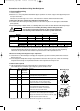
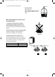
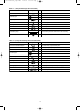
Table 1-3 (2-Way Air Discharge Semi-Concealed)
Part Name Figure
Q’ty
Remarks
Flare insulator
2
Insulating tape
2
Vinyl clamp
8
Hose band
1
Packing
1
Drain insulator
1
For wide and narrow tubes
For wide and narrow tube flare nuts
For flare insulator and drain insulator
For securing drain hose
For drain joint
F
or drain joint
(White)
Drain hose (L = 25cm)
Special washer
For suspension bolts
For securing drain hose
1
1
4
8
1
1
For sealing recessed portion of power supply
Putty
Installation gauge
(Use the packaging side pad.)
M5 × L40
(Black screw, with washer)
Gauge A
(Install on tubing side.)
Gauge B
(Install on opposite side of tubing.)
For fastening
installation gauges
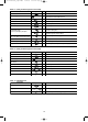
Table 1-4 (4-Way Air Discharge Semi-Concealed)
Part Name Figure
Q’ty
Remarks
Full-scale installation diagram
1
Flare insulator
2
Insulating tape
2
Hose band
1
Packing
1
Drain insulator
1
Drain hose
1
4
For wide and narrow tubes
For securing drain hose
For drain joint
For dr
ain joint
(White)
Washer
8
For suspension bolts
Screw
Printed on container box
For wide and narrow tube flare nuts
For full-scale installation diagram
For securing drain hose
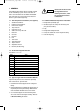
Table 1-5 (Wall-Mounted)
Part Name
Figure
Q’ty
Remarks
Plastic cover
1
Tapping screw
10
For improved tubing appearance
For fixing the rear panel
Truss-head Phillips
4 × 16 mm
Insulator
1
For insulating flare nut (73 type only)
04-396 Inverter-W_a-p50 ARGO 12/21/04 9:38 AM Page 10