926 Sno-Thro 0 Service Manual Models 926001, 002, 003, 004, 005, 006, 007, 008, 009, 010, 011, 012, 101, 102, 103, 300, 301, 302, 303, 304, 500, 501, 504 02983600 06/07 Printed in USA
TABLE OF CONTENTS SAFETY . . . . . . . . . . . . . . . . . . . . . . . . . . . . . . . . . . 5 STORAGE . . . . . . . . . . . . . . . . . . . . . . . . . . . . . . . 31 ASSEMBLY . . . . . . . . . . . . . . . . . . . . . . . . . . . . . . . 9 SERVICE PARTS. . . . . . . . . . . . . . . . . . . . . . . . . . 31 CONTROLS AND FEATURES . . . . . . . . . . . . . . . 13 ACCESSORIES . . . . . . . . . . . . . . . . . . . . . . . . . . . 31 OPERATION . . . . . . . . . . . . . . . . . . . . . . . . . . . . .
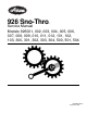
DISCLAIMER Ariens reserves the right to discontinue, make changes to, and add improvements upon its products at any time without public notice or obligation. The descriptions and specifications contained in this manual were in effect at printing. Equipment described within this manual may be optional. Some illustrations may not be applicable to your unit.
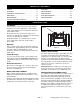
SAFETY DECALS AND LOCATIONS 2. DANGER! ALWAYS replace missing or damaged Safety Decals. Refer to figure below for Safety Decal locations. 1 OS6610 2 ROTATING PARTS! ONLY use clean-out tool to clear blockages. NEVER use your hands. High speed impeller rotates below discharge opening. Wait for all moving parts to stop before removing clogs or servicing. 3. DANGER! 3 ROTATING PARTS. Keep clear of auger while engine is running. OS2080 • Read Operator’s Manual.
Check for weak spots on docks, ramps or floors. Avoid uneven work areas and rough terrain. Stay alert for hidden hazards. ALWAYS disengage attachment, stop unit and engine, remove key and allow moving parts to stop before leaving operator’s position. Avoid uneven and rough terrain. DO NOT operate near drop-offs, ditches, or embankments. Unit can suddenly turn over if a wheel is over the edge of a cliff or ditch, or if an edge caves in. ROTATING IMPELLER CAN CAUSE SERIOUS INJURY.
DO NOT operate on steep slopes. DO NOT clear snow across the face of slopes. Keep all movement on slopes slow and gradual. DO NOT make sudden changes in speed or direction. Use a slow speed to avoid stops or shifts on slopes. Avoid starting or stopping on a slope. DO NOT park unit on a slope unless absolutely necessary. When parking on a slope always block the wheels. ALWAYS shut off engine, remove key, and close fuel shut-off valve or drain fuel when transporting unit on a truck or trailer.
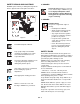
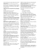
ASSEMBLY WARNING: AVOID INJURY. Read and understand the entire Safety section before proceeding. Unfold Handlebar (Figure 4) 1. Remove the lower and loosen the upper wing knobs on the handlebar assembly. 2. Loosen the wing nuts on the shift rod. 3. Put the speed selector lever in the first forward position. WARNING: Dropping or tipping over boxed unit could result in personal injury or damage to unit. 4. Rotate the handlebars into operating position. 5.
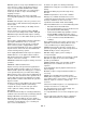
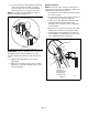
NOTE: After the chute rod has been inserted through the hex hole in the control assembly, placing the unit in the service position (see Service Position on page 19) will ease alignment and installation of the hair pin. 5. Secure the chute rod to the control assembly with the hair pin removed in step 3 using the proper hole location as shown in Figure 7. Insert the hair pin with the loop end to the left of the chute rod so the control assembly follows a full range of travel. 1 3 2 2 3 4 1 4 1 1.
6. Insert the chute lock cable fitting into the bracket on the chute pedestal, and then connect the chute lock cable to the lock teeth by fitting the cable ball end into the slot on the lock teeth. Deflector Remote NOTE: Connect the cable end to the cable anchor on the discharge deflector before clipping the cable to the cable bracket on the discharge chute. NOTE: Press down on lock teeth with your finger to align the cable ball end with the slot. 1.
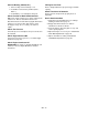
Connect Battery (926500, 501) Fill Engine Fuel Tank 1. Remove wing nuts from battery cover. Refer to Engine Manual for proper fuel type and tank capacity. 2. Install wire leads to battery terminal (Red + , Black -). Check Function of all Controls 3. Install battery cover and tighten wing nuts. Ensure unit runs and performs properly. Refer to Operation. Check Function of Dual Handle Interlock Without the engine running, press down (engage) both clutch levers. Release attachment clutch lever.
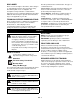
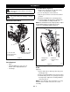
CONTROLS AND FEATURES 2 1 3 5 4 1. Attachment Clutch Lever 6 2. Speed Selector 7 3. Deflector Remote Control 8 4. Chute Control 9 35 5. Traction Drive Clutch Lever 6. Oil Fill/Dipstick 10 34 7. Muffler Guard 8. Discharge Chute Deflector 11 33 9. Discharge Chute 10. Impeller 32 11. Clean-out Tool 31 12. Auger 12 30 29 28 25 24 13 15 26 14. Auger Gearcase 15. Recoil Starter Handle 16.
OPERATION Ignition Switch (120V or 240V start on engine) WARNING: AVOID INJURY. Read and understand the entire Safety section before proceeding. Key Switch has two positions: 1. “Stop” - pulled out WARNING: To avoid injury to hands and feet, always disengage clutches, shut off engine, and wait for all movement to stop before unclogging or working on snow thrower. Keep hands and feet away from auger and impeller. 2 2. "Run" - pushed in 1 NOTE: DO NOT twist key after it is inserted.
Throttle The throttle controls the engine speed. To increase or decrease the engine speed, adjust to: 1 Discharge chute rotates 200°. 1. Fast (normal or warm starts) ALWAYS position discharge chute in safe direction and angle, away from operator and bystanders, before starting engine. 3 2. Part-Throttle Discharge Chute Control 4 3. Slow IMPORTANT: If chute does not stay in set position, adjust as directed in SERVICE AND ADJUSTMENTS on page 23, or repair before operation.
If remote wheel lock does not lock or unlock properly, adjust or repair before operation (see REMOTE WHEEL LOCK (926002, 003, 102, 103, 302, 303, 304) on page 24). 1 Axle Lock Pin (Figure 13) (926001, 101, 504) Use the axle lock pin to lock or unlock the right or left wheel. Lock both wheels to increase traction; unlock one wheel to allow for easier turning of the unit. NOTE: Unit will not drive with both wheels unlocked. Wheel Unlocked 2 Wheel Locked Axle Lock Pin 1. Stored Position 2.
3. Clean Fuel Cap and surrounding area to prevent dirt from entering Fuel Tank. 5. Check Remote Wheel Lock (926002, 003, 102, 103, 302, 303, 304) 4. Remove Cap. Squeeze and release the remote wheel lock to lock the left wheel for better traction when throwing snow or to unlock the left wheel for easier steering. IMPORTANT: DO NOT use gasohol or gasoline containing alcohol. See Engine Manual for correct type and grade of fuel. 5. Fill fuel tank to within 1/2 in. (1.
12. Set throttle to Part Throttle or Slow position for travel or adaptation to outside temperature. Set throttle to Fast position for normal operation. (All models except 926007) NOTE: When temperature is below -15° F (-26° C) additional priming may be needed. 4. If engine is cold, apply choke. See Engine Manual for detailed instructions. NOTE: A warm engine requires less choking than a cold engine. Electric Start (12V) 1. Turn discharge chute straight ahead. 5. Set throttle to proper starting position.
Tips for Operation TRAVELING Snow is best removed as soon as possible after snow fall. To travel from one work area to another: 1. Set Throttle to Slow or Part-Throttle position. To clear an area, run unit in an overlapping series of paths. For large areas, start in the middle and throw snow to each side, so snow is not cleared more than once. 2. Press down on handlebars enough to raise front of unit slightly off surface. ALWAYS direct snow away from area to be cleared and with direction of the wind.
MAINTENANCE SCHEDULE Service Position The chart below shows the recommended maintenance schedule that should be performed on a regular basis. More frequent service may be required. MAINTENANCE SCHEDULE Service Performed Each Use Check Dual Handle Interlock • Check Fasteners • Check Clutch Operation • Check Clutch Spring Adjustments Clean Engine Check Engine Oil Change Engine Oil Figure 16 OS7120 Every 5 hrs. Every 25 hrs.
CHECK ENGINE OIL The engine crankcase oil should be checked every 5 hours of operation. Oil level MUST be maintained in safe operating range on dipstick at all times or engine damage will result (See Engine Manual). GENERAL LUBRICATION IMPORTANT: Wipe each fitting clean before and after lubrication. Do not wipe gearcase filler plug; wiping the gearcase filler plug may remove thread sealant and cause leaks. Park unit on a level surface. Refer to Engine Manual for detailed instructions.
2 1 OS0642 OS7135 OS7140 OS7150 1 1 1 Grease Figure 18 GB - 22 Oil
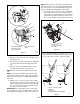
SERVICE AND ADJUSTMENTS WARNING: AVOID INJURY. Read and understand the entire Safety section before proceeding. 1 RUNNERS Runners should be adjusted as conditions require (Figure 19). 1. Position unit on a hard, flat, smooth level surface. 2 2 2. Adjust runners by inserting a spacer of desired thickness under center of scraper blade, loosen runner hardware, slide runners to flat surface. Allow 1/8 in. (3 mm) between scraper blade and hard smooth surfaces. Allow 1-1/4 in.
1 REMOTE DIFFERENTIAL (926004, 005, 006, 300, 301, 500, 501) 2 1 If remote differential does not lock: 1. Place unit in service position (see Service Position on page 20). 2 2. Remove bottom cover. 3. Loosen jam nuts on cable. Make sure the bottom jam nut is loosened enough to remove slack from cable. 3 4. Pull the cable adjuster to remove slack between the cable adjuster and the extension spring and hold the cable adjuster in position while tightening the top jam nut against the unit frame.
5. Loosen the top jam nut 1 – 3 turns. 6. Tighten the bottom jam nut. 7. Re-install bottom cover. Tighten nut. 8. Check function of remote wheel lock. If wheel lock does not function properly, take unit to Dealer for repairs. Finger tighten top jam nut, then loosen top jam nut 1 – 3 turns. 3 1 2 No Slack 1 1. Adjusting Nuts 2. Cable Support Bracket 1. Top Jam Nut 2. Bottom Jam Nut 3.
ATTACHMENT CLUTCH/BRAKE ADJUSTMENT (Figures 31, 32 and 33) If chute does not rotate freely: Tighten the cable by loosening the upper adjustment nut, and then tightening the lower adjustment nut against the bracket (Figure 27). IMPORTANT: IMPROPER ADJUSTMENT could result in unexpected movement of auger and impeller causing death or serious injury. Auger / impeller must stop within 5 seconds when Attachment Clutch/Impeller Brake lever is released. Loosen upper adjustment nut.
Adjust the Attachment Clutch Cable Spring Extension 4. Tighten jam nut on cable adjustment barrel. Check Attachment Idler Arm Roller Clearance 1. With the attachment clutch lever disengaged, measure the length of the clutch cable spring. NOTE: It will be difficult to check the measurment inside the frame. Use a 1/2 in. (12.7 mm) minimum spacer as a gauge to check the clearance between the roller and the frame. 2.
2. Check belt finger clearance (Figure 36). 1 2 With clutch lever engaged, belt finger on the side opposite the belt idler should be less than 1/8 in. (3 mm) from belt, but not touching the belt. Adjust belt finger as necessary. 3 3. Replace bottom cover. 4. Replace belt cover. TRACTION DRIVE CLUTCH ADJUSTMENT If drive slips, adjust traction clutch to compensate for friction disc wear. To adjust traction clutch: 1. Place speed selector in fastest forward speed. 3 2. Place unit in service position. 3.
7. Remove hex bolts securing housing to frame. Tip housing and frame apart on pivot pins (Figure 35). 5. Adjust spring extension. a.With the traction drive clutch lever disengaged, loosen the jam nut on the cable adjuster. b.Turn the adjuster body up the cable for more spring extension. c.Turn the adjuster body down the cable for less spring extension. d.Finger tighten the jam nut, and then hold the adjuster body with pliers and tighten the jam nut with wrench. 6.
FRICTION DISC REPLACEMENT Install new attachment drive belt: 1. Place new attachment belt onto attachment pulley. 1. Place unit into service position. 2. Remove bottom cover by removing six hex bolts. NOTE: Holding down the attachment clutch lever will make it easier to reconnect the housing and frame. 3. With axle locked, hold one wheel so friction disc will not rotate and remove three cap screws holding friction disc to carrier. 2. Tip housing and frame back together and secure with hex bolts. 4.
BATTERY (926500, 501) SERVICE PARTS Charging 1. Place unit on a level surface and shut off engine. Order the following parts through your Dealer: Part No. Description 2. Disconnect negative (-) cable first, then positive (+) cable. 00036800 Hi-Temp Grease (3, 3 oz. cartridges) 3. Loosen wing nut and remove battery. Place battery on bench or other well ventilated place. 07200020 Impeller Belt (926001, 004, 005, 101, 102, 300, 301, 304) 21533500 Spark Plug 4.
ENGINE ENGINE TROUBLESHOOTING The following troubleshooting chart is to be used to isolate engine problems and give possible causes and corrective action responses. TROUBLE Black Exhaust Blue/White Exhaust Difficult Starting Erratic Running Excessive Fuel Consumption High Oil Pressure Knocking Loss of Power or System Low Cranking Power Low Oil Pressure Misfiring Overheating Poor Compression Starts and Stops The troubleshooting key is generic and can be used for several types of engines.
See your engine manual for information on the operation and maintenance of your engine. Follow those instructions for oil and filter changes. REMOVING THE ENGINE 1. Drain gasoline. 11.Remove both belts from the engine pulleys. Remove pulleys. 12.If the unit has a bracket at the top of the engine for chute/deflector controls, unbolt it. 13.If the unit is equipped with electric starting, remove the starter.
INSTALLING THE ENGINE 1. Position the engine in the frame. 15.Insert mounting bolts and tighten. 16.If equipped with electric starting, install the starter. On models with 12V starter (926500, 501) connect the positive lead from the solinoid to the starter. 17.Reattach any brackets for chute/deflector controls. 18.Install pulleys on engine shaft. Do not tighten set screws. 19.Install belts. Adjust the engine pulleys to align with attachment and drive pulleys. Tighten set screws.
ENGINE AND BELT DRIVE Model 926001, 002, 003, 004, 005, 006, 101, 102, 103, 300, 301, 302, 303, 304, 500, 501, 502, 504 26 34 24 9 22 22 1 2 37 36 7 8 31 35 23 11 38 32 4 12 33 41 6 41 40 39 10 19 21 20 34 15 18 30 17 22 28 16 13 29 PS1082 GB - 35
Model 926007, 008, 009, 010, 011, 012 27 25 4 9 44 22 1 2 43 1 22 42 2 7 8 37 31 36 23 11 38 32 35 12 45 4 33 41 6 41 40 39 10 19 21 20 34 15 18 30 17 22 28 16 13 29 PS1082 GB - 36
ENGINE AND BELT DRIVE Model All Item Part No. Qty.
WHEELS, AXLE AND REDUCTION DRIVE WHEELS AND AXLE The wheels are held onto the axle with locking pins. To remove a wheel pull the locking pin and the wheel will slide off. To remove the axle: 1. Place the unit in upright service position. 20.Remove the bottom plate. 21.Remove both wheels. 22.Drive out roll pin. 23.The axle will slide out either side. NOTE: Make a record of the positions for the washers and flanges for reassembly. To install the axle: 1.
WHEELS AND AXLES Model 926001, 007, 101, 504 1 14 2 4 3 8 3 13 5 12 10 7 4 5 11 3 3 9 8 tem 1 2 3 4 5 6 7 8 9 10 11 12 13 14 Part No. 07100034 07100035 07015800 06436300 00275100 07412000 06601200 00371000 05500030 00531500 00391500 05803000 07100039 07156400 07100104 Qty. 1 1 2 5 2 6 1 1 2 1 1 2 2 2 1 6 PS0803 Description Tire/Wheel Assembly, RH 15 x 5 - 6 Pin (Includes Items 12-14) Tire/Wheel Assembly, LH 15 x 5 - 6 Pin (Includes Items 12-14) Pin-LOK .31 x 2.00 Washer, Flat Steel 1.
WHEELS AND AXLES Model 926004, 005, 006, 008, 010, 012, 300, 301, 500, 501, 502 1 18 4 12 11 3 13 2 5 17 9 16 10 6 13 4 8 14 11 14 7 3 PS0802 15 item 1 2 3 4 5 6 7 8 9 10 11 12 13 14 15 16 17 18 Part No. Qty.
WHEELS AND AXLES Model 926002, 003, 009, 011, 102, 103, 302, 303, 304 1 24 4 3 18 14 19 3 5 2 15 21 15 23 16 17 22 20 14 13 10 9 20 7 8 3 18 4 3 12 3 6 11 13 5 tem 1 Part No. Qty.
REDUCTION DRIVE Model All 926007, 008, 009, 010, 011, 012 11 14 10 16 15 12 21 14 3 2 21 19 18 7 2 13 12 11 7 7 17 10 1 2 2 5 4 8 7 5 9 6 PS0464 20 Item Part No. Qty.
CHUTE/AUGER/IMPELLER AUGER/IMPELLER REMOVAL Place unit in the belt service position. 1. Remove set screw holding auger driven pulley to shaft and remove pulley. 36.Remove three nuts holding bushings to housing on each side. 37.Grasp auger assembly and pull gear case and auger/impeller assembly free of housing. 38.Remove bearing flanges. 39.Remove shear bolts and remove auger from shaft. 40.Check all parts for wear or replacement. 41.Assemble using reverse procedure.
RUNNERS CAUTION: Adjust auger/impeller housing height to clear gravel or crushed rock surfaces. Runners should be adjusted as conditions require. Raising or lowering runners controls distance scraper blade is held above surface being cleared. When operating machine on gravel surface, lower runners so the housing will not pick up gravel. On concrete, blacktopped or packed down snow surfaces, raise runners so that scraper blade scrapes clean. Position unit on a flat level surface.
CHUTE, AND AUGER AND BATTERY Model All 50 49 41 1 40 43 13 7 46 6 2 48 45 3 33 35 36 47 54 55 56 29 15 39 8 29 42 52 53 51 14 34 38 32 37 44 11 27 57 31 4 10 30 5 25 24 26 21 27 20 9 17 19 16 12 20 18 28 22 23 PS1092 GB - 45
CHUTE, AND AUGER AND BATTERY Model All 926007, 008, 009, 010, 011, 012 Item Part No. Qty. Description 1 2 3 00389000 04912900 1 1 A/R 4 5 02488659 06220400 1 2 6 06437300 6 7 06537500 2 8 9 03679000 05946800 1 4 10 06530100 4 11 12 02484459 06435900 1 4 13 14 08300013 07412000 1 2 15 52600200 1 Rod, Deflector Cap Cover, Battery (500, 501) Battery Recommend 240 Minimum CCA at 0° F. Size U1R or U1L (500, 501) Battery Tray (500, 501) Bolt, Round Head Square Neck .25-20 x 7.
CHUTE, AUGER AND BATTERY Model All Item 37 38 39 40 41 42 43 44 45 46 47 48 49 50 51 52 53 54 55 56 57 Part No. 07028500 07053300 01014200 06900018 52602200 05947900 06909400 07533200 05947300 00170200 00170300 06813600 06437300 06701900 06536700 06310500 06308600 05946800 06439500 06308400 06533200 Qty. 2 2 1 1 1 2 1 2 1 1 1 2 1 1 2 2 2 2 2 2 2 Description Bolt, Hex Flanged Whizloc Head .38-16 x .75 Nut, Retainer .375-16 x .37 Bearing Flange Cable, Deflector Chute, Discharge with Deflector Bolt, Hex .
DISCHARGE CHUTE Model All 3 16 2 1 4 15 5 6 7 22 21 8 9 20 19 18 12 10 11 17 13 14 PS1103 Item 1 2 3 4 5 6 7 8 9 10 11 12 13 14 15 16 17 18 19 20 21 22 Part No. Qty. 00389200 00261700 07412000 05952500 00184200 06222300 06400014 05500027 06441400 00184300 06543500 05500005 05958500 06308800 06944800 06712900 00388551 08300014 06543500 06426600 00180900 05500024 1 1 1 1 1 1 1 1 2 1 1 1 2 2 1 1 1 1 1 1 1 1 Description Rod, Chute Rotation - Hex Cover, Chute Gear Screw, Tapping .25-20 x .
GEAR CASE ALUMINUM GEAR CASE 1. Remove auger/impeller and gear case from housing referring to Auger/Impeller Section. 44.Removesix bolts that hold right and left gear case halves together. 45.If flange bushings need replacement, first remove seals from outside of gear case halves with a screwdriver. Flange bushings can then be pressed out from outside in with a bearing driver. Bushings are very lightly pressed in. 46.
GEAR CASE-ALUMINUM Model 926001, 002, 003, 007, 009, 011, 101, 102, 103, 302, 303, 304, 504 7 2 5 3 1 20 10 21 9 6 4 11 12 8 16 19 13 9 11 16 17 21 18 14 15 PS0283 Item 1 2 3 4 5 6 7 8 9 10 11 12 13 14 15 16 17 18 19 20 21 Part No. Qty.
GEAR CASE-CAST IRON Model 926004, 005, 006, 008, 010, 012, 300, 301, 500, 501 2 1 23 1 21 4 6 7 3 22 8 5 13 17 11 20 16 12 17 15 16 9 14 13 19 20 12 10 18 PS0472 GB - 51
GEAR CASE-CAST IRON Model 926004, 005, 006, 008, 010, 012, 300, 301, 500, 501 Item 1 2 3 4 5 6 7 8 9 10 11 12 13 14 15 16 17 18 19 20 21 22 23 Part No. 05803700 00258251 00258451 52419600 05806800 05500008 05600002 00255100 00388200 00425200 05500007 00388400 05947900 05618800 00393500 00425100 05520500 06416600 06600800 00257500 00275000 00276100 00267500 06306800 52600700 52600800 52600900 52601000 00150900 00008000 Qty.
ELECTRICAL Model 926002, 003, 004, 005, 006, 008, 009, 010, 011, 012, 102, 103, 300, 301, 302, 303, 304, 500, 501, 502 13 2 8 9 12 6 3 4 10 5 11 12 7 1 PS0891 GB - 53
13 8 9 12 10 12 14 7 1 PS0891 item Part No. Qty. 1 2 3 4 5 6 7 07517300 AR 02460700 1 07517700 1 06517300 1 02739600 1 52709300 1 00432300 AR 8 9 10 11 12 13 14 00432400 AR 06403800 1 06310900 1 02485700 1 00524700 1 07532900 2 09207600 AR 00483200 1 Description Cable Tie Key with Cap (500, 501) Cap, Ignition Switch (500, 501) Nut, Panel .
CONTINUITY DIAGRAM Model 926500, 501 Key Switch (02739600) Hand Warmer Switch (02485700) Solenoid (Top View) (03679000) PS0841 GB - 55
CONTINUITY AND WIRING DIAGRAMS Model 926002, 003, 004, 005, 006, 008, 009, 010, 011, 012, 102, 103, 300, 301, 302, 304, 502, 503 HEAD LIGHT 1 1 2 BLACK HAND WARMER SWITCH 3 BROWN/ORANGE YELLOW D.C. CHARGE RED ENGINE GROUND 4 4 1 1 2 2 3 3 BROWN/ORANGE YELLOW A.C. LIGHTING 2 4 YELLOW 1 1 2 2 RIGHT HAND WARMERS 1 1 2 2 LEFT BLACK BLACK PS0830 Item Part No. 1 2 00487500 07532900 Qty.
WIRING DIAGRAM Model 926500, 501 HEAD LIGHT 1 1 2 2 HAND WARMER SWITCH BROWN / ORANGE YELLOW A.C. LIGHTING ENGINE D.C. CHARGE YELLOW RED MAGNETO GROUND 4 4 1 1 2 2 3 3 8 BROWN/ORANGE BLACK 5 YELLOW PURPLE WHITE / BLACK M STARTER BLACK BLACK RED 3 1 1 2 2 RIGHT HAND WARMERS 1 1 2 2 LEFT BLACK 2 G A BATTERY RED R BLACK B RED 4 7 A B RED FUSE 15 AMP A 6 S COIL 2 KEY SWITCH COIL 1 BROWN STARTER SOLENOID BLACK PS0672 Item Part No.
ELECTRICAL AND WIRING DIAGRAM Model 926001, 007, 101, 504 1 2 PS0900 Item Part No. Qty.
TROUBLESHOOTING PROBLEM Engine will not crank/start. PROBABLE CAUSE CORRECTION 1. Fuel tank is empty. 1. Fill fuel tank. 2. Fuel shut-off valve closed. 2. Open fuel shut-off valve. 3. Build up of dirt and residue around governor/carburetor. 3. Clean area around governor/carburetor. 4. Key Switch not in run position. 4. Put Key Switch into run position. 5. Ignition switch starter circuit not functioning. 5. Check for a bad starter or connections. 6. Battery discharged, wires loose. 6.
SPECIFICATIONS Model Number 926001 926002 926003 Description ST926LE ST11528LE Engine - Tecumseh LH318SA OH318SA Power Max - HP (kW) 9.0 (6.7) 11.5 (8.6) 13.0 (9.7) Fast Idle Speed RPM (min-1) Displacement in. (cc) Electric Start 926004 926005 ST1332LE ST926DLE ST11526DLE OH358SA OH318SA OH318SA 9.0 (6.7) 11.5 (8.6) 19.4 (318) 19.4 (318) 19.4 (318) 120V 120V 120V 3600 ± 150 19.4 (318) 19.4 (318) 120V 120V Fuel See Engine Manual Tank Capacity qt (Liters) 4 (3.8) 4 (3.
SPECIFICATIONS Model Number 926006 926101 926102 926103 926300 926301 Description ST1328DLE 926LE 11528LE 1332LE ST11526DLE ST926DLE Engine - Tecumseh OH358SA LH318SA OH318SA OH358SA OH318SA OH318SA Power Max - HP (kW) 13.0 (9.7) 9.0 (6.7) 11.5 (8.6) 13.0 (9.7) 11.5 (8.6) 9.0 (6.7) Fast Idle Speed RPM (min-1) Displacement in. (cc) Electric Start 3600 ± 150 21.8 (358) 19.4 (318) 19.4 (318) 19.4 (318) 19.4 (318) 19.
SPECIFICATIONS Model Number 926302 926303 926304 926500 926501 926504 Description ST1332LE ST1328LE ST11528LE ST1332DLE ST1336DLE ST8526LE Engine - Tecumseh OH358SA OH358SA OH318SA OH358SA OH358SA LH318SA Power Max - HP (kW) 13.0 (9.7) 13.0 (9.7) 11.5 (8.6) 13.0 (9.7) 13.0 (9.7) 8.5 (6.3) Fast Idle Speed RPM (min-1) Displacement in. (cc) Electric Start 3600 ± 150 21.8 (358) 21.8 (358) 19.4 (318) 21.8 (358) 21.8 (358) 19.
SPECIFICATIONS Model Number 926007 926008 926009 926010 926011 926012 Description ST926LE ST926DLE ST11528LE ST11526DLE ST1332LE ST1328DLE Engine - Briggs 20A1140120E1 20B4140121E1 Power Max - HP (kW) 9.5 (7.0) 9.5 (7.0) 21C3140116E1 21C3140116E1 21B4140117E1 21B4140117E1 11.5 (8.6) Fast Idle Speed RPM (min-1) Displacement in. (cc) Electric Start 11.5 (8.6) 13.0 (9.7) 13.0 (9.7) 3600 ± 100 18.64 (305) 18.64 (305) 20.85 (342) 20.85 (342) 20.85 (342) 20.
Ariens Company 655 West Ryan Street P.O. Box 157 Brillion, WI 54110-0157 920-756-2141 Fax 920-756-2407 www.ariens.