Zoom ® Owner/Operator Manual Manuel Du Proprietaire/Utilisateur Models 915131 - Zoom 34 915141 - Zoom 42 915143- Zoom 50 915151 - Zoom 34 Carb 915155 -Zoom 42 Carb ENGLISH 04096200 ,_ _ (_ FRANQAIS 5/10 Printed in USA
SAFETY .......................... 4 STORAGE ....................... ASSEMBLY ....................... 9 TROUBLESHOOTING CONTROLS AND FEATURES OPERATION ..................... MAINTENANCE SERVICE ....... SCHEDULE ........ AND ADJUSTMENTS NON-ENGLISH ..... 11 SERVICE 12 ACCESSORIES 16 SPECIFICATIONS 18 WARRANTY MANUALS -_ PARTS ................. ................... ................. ..................... 29 30 32 English may your be obtained from your Dealer. Visit dealer or www.
Record UnitModel andSerial DELIVERY numbers here. Customer Note: If you have purchased this product without complete assembly and instruction by your retailer, it is your responsibility to: Record Engine Model and Serial numbers here. Read and understand all assembly instructions in this manual. If you do not understand or have difficulty following the instructions, contact your nearest Ariens Dealer for assistance.
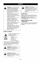
[,.'_-,1 _1=11"4 WARNING: This cutting machine is capable of amputating hands and feet and throwing objects. Failure to observe the safety instructions in the manuals and on decals could result in serious injury or death. HAZARDOUS SITUATION! If not CAUTION: POTENTIALLY avoided, MAY RESULT in minor or moderate injury. It may also be used to alert against unsafe practices. NOTATIONS Slopes are a major factor related to loss-of-control and tip-over accidents. Operation on all slopes requires extra caution.
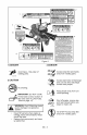
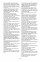
Figure 2 1.DANGER! &DANGER! # Avoid - Stay clear of rotatinginjury parts. OL1816 Always keep feet and hands away from rotating parts. OL1809 2.CAUTION Always stand clear of discharge area. Do not direct discharge toward other people. No smoking. IMPORTANT: D:Ltt DO NOT overfill. i_ filler neck (see FILLING FUELof Fill fuel tank to below bottom TANK on page 13). ,_ severe damage evaporative WARNING: OvertoFilling may cause system ! while Keep operating.
4.DANGER! TO AVOID SERIOUS INJURY OR DEATH Read the operator's &WARNING! manual. Always stand clear of discharge area. OL1814 OLt801 Keep children and others away from unit while operating. DJ Do not operate mower unless bagger is attached or guards are in operating position. OL1802 J__L"_ -,--;_r.._ OLI8t5 Never direct discharge toward other people. Thrown objects can cause injury. &DANGER! --%L_3 Keep hands and feet away. Lookwhile downbacking. and behind before and OL1804 _ii_.
Read, understand, andfollow allsafety Protect eyes, faceandhead fromobjects that practices inOwner/Operator Manual before maybethrown fromunit.Wear appropriate assembling, using orworking onthismower. hearing protection. Always wear safety orsafety glasses withsideshields ALWAYS remove keyfromignition andwire goggles operating mower. fromspark plugbefore assembly, orworking when onthisunit. Avoid sharp edges. Sharp edges cancut. Moving parts cancutofffingers orahand.
Donotoperate without either entire grass Use extra care when loading or unloading unit onto trailer or truck. catcher orthedischarge guard inplace. DONOT operate inreverse unless absolutelySecure unit chassis to transport vehicle. necessary. ALWAYS lookdown andbehind NEVER secure from rods or linkages that before andwhile backing; especially for could be damaged. children. DO NOT transport machine while engine is Follow themanufacturer's recommendations running.
Explosive Gases frombattery cancause Fumes fromengine exhaust cancause injury death orserious injury. Poisonous battery ordeath. DONOTrunengine inanenclosed fluidcontains sulfuric acid anditscontact with area. Always provide good ventilation. skin,eyes orclothing cancause severe ALWAYS maintain unit i nsafe operating chemical burns. condition. Damaged orworn outmuffler can NOflames, NOsparks, NOsmoking near cause fireorexplosion. battery.
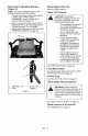
Place Unit in Operating Position (Figure 3): NOTE: The seat is shipped with the seat positioned as far back as possible. 1. Tip seat forward and adjust the seat as needed (see TIPPING SEAT FORWARD on page 18 and SEAT ADJUSTMENT on page 18). 2. Remove eccentric spacers and rotate steering levers to the operating position. Reinstall spacers. Do not tighten. 3. Adjust steering levers (see ADJUSTING STEERING LEVERS on page 24). Check Engine Oil Level Refer to Engine Manual.
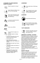
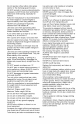
[_o]_jij_[o]l_,.']r-'__,I n_] I_1_-'_nt_"] 6 4 7 5 11 8 10 915131, 915141 9 13 915143 Figure 4 1. 2. 3. 4. 5. Throttle/Choke Lever ( 915131, 141 ) Ignition Switch PTO Switch Seat Fuel Level 6. Steering Levers 7. Fuel Tank 8. Mower Lift Pedal 9. Mower Deck 10. 11. 12. 13.
Safety Interlock System Read and understand the entire WARNING: AVOID INJURY. Safety section before proceeding. ,_ WARNING: Safety interlock failure and improper operation of unit can result in death or serious injury. Check system before each use to make sure it is functioning properly. CONTROLS AND FEATURES See figure 4 for all controls and features locations. Perform the following tests to ensure the safety interlock system is working properly.
Power Take-Off (PTO) Switch o 2 1 Engages (2) and disengages blades. Steering 3 (1) mower 1. Mower Lift Pedal Levers Reverse (1)backward. 3. Figure 5 Pull both steering levers Forward (2) - Push both steering levers forward. Left (3) - Pull left steering lever back or push right steering lever forward or a combination of both. Adjustment Hole Adjustment Pin NOTE: The adjustment pin is used to set the height of the mower deck. See SPECIFICATIONS on page 30 for cutting height dimensions.
GASOLINE STARTING AND SHUTTING OFF ENGINE IMPORTANT: ALWAYS use gasoline that meets the following guidelines: Clean, fresh gasoline. A minimum of 87 octane/87 AKI (91 RON). High altitude use may require a different octane. Consult your engine manual. Gasoline with up to 10% ethanol (gasohol) or up to 10% MTBE (methyl tertiary butyl ether) is acceptable. Use of any gasoline other than those approved above will void the engine warranty.
TRANSPORTING UNIT MOVING UNIT MANUALLY ALWAYS shut off engine, set parking brake, remove key, and drain fuel when transporting unit on a truck or trailer. Tie unit down securely. Do not tie down by linkages, guards, cables or other parts that may be damaged. ,_ or bypass transmission WARNING: DO NOT disengage and coast downhill. Pull the bypass lever out and lock it in place, and then release the parking brake to push the unit by hand. FOR BEST PERFORMANCE Cut grass when it is dry.
WARNING: and understand AVOID theINJURY. entire Safety Read section before proceeding. IMPORTANT: Proper maintenance can prolong the life of unit. The following chart shows the recommended service schedule. Refer to the maintenance instructions in the Engine Manual for additional information. NOTE: To have full access to the engine, the seat must be tipped forward (see TIPPING SEAT FORWARD on page 18) and the hood opened (see MOWER DECK REMOVAL AND INSTALLATION on page 18). nterval .Taski.
nterval .Taski.Action Each Use Follow Engine Manual Maintenance Schedule 25 Hours 3r Every Season Check Battery Keep battery and battery terminals clean (see Cleaning Battery and Battery Cables on page 23). Lubricate Unit Apply grease to zerk (1) on each front wheel 50 Hours or Every Season Check Fasteners Check mower blade mounting hardware and all other fasteners. Replace fasteners that are missing or damaged. Tighten all nuts and bolts to the correct torque value.
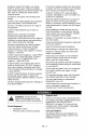
_.'_i[o]_r:1 _Il_Wll_ll_l|_v_ I=I_i__] MOWER DECK REMOVAL AND INSTALLATION Read and understand the entire WARNING: AVOID INJURY. Safety section before proceeding. 915131: Remove (Figure TIPPING SEAT FORWARD Put steering levers up and tip seat forward (figure 7). 1. 2. 3. 1. Seat Tipped Forward 2. Mounting Hardware Cable Anchor PTO Actuator Cable Idler Arm Figure 7 SEAT ADJUSTMENT Figure 8 NOTE: Perform steps 3 and 4 for the right and left side of unit. 1. Tip the seat forward. 2.
915131: 4. Connect the PTO actuator cable to the deck idler arm and cable anchor. Install (Figure 9) 1. Slide mower deck under unit. NOTE: Perform step 2 and 3 for the right and left side of unit. 2. Connect drag link to front deck bracket. 3. Connect front and rear trunnions to lift arms. 1 5. Install PTO belt on the engine drive pulley (see REPLACING PTO BELT on page 25). NOTE: Make sure the cable is taut, but not tight. The cable needs a slight amount of slack for the pulley brake to work correctly.
915141, 3. Connect front and rear trunnions to lift arms. 143: Install (Figure 10) 1. Slide mower deck under unit. 4. Install PTO belt on the engine drive pulley (see REPLACING PTO BELT on page 25). 5. Level and adjust pitch of mower deck (see LEVELLING AND ADJUSTING PITCH OF MOWER DECK on page 20). NOTE: Perform step 2 and 3 for the right and left side of unit. 2. Connect drag link to front deck bracket. 5 4 1. 2. 3. 2 3 Rear Trunnion PTO Belt Mower Deck 4. 5. 6.
The Forward Pitch Of The Mower Blades (Figure 12): Should be 0.0 in. (0.0 mm) to 1/4 in. (6.35 mm) pitched forward. NOTE: This measurement must be taken when the mower blades ends point forward. Forward Pitch of Mower Blades 3 1 2 Adjusting The Mower Deck To Adjust Mower Blade Height And Pitch (Figure 14): NOTE: Adjusting the mower deck will adjust the height and pitch of the mower blades. 1.
4. Install mower blade on unit (see REPLACING MOWER BLADE on page 21 ). DO NOT Sharpen to this Pattern 3 Sharpen to this Pattern j4 1. 2. Spindle Blade 3. Washer 4. 5/8in.Nut Figure 15 SHARPENING MOWER BLADE 1 1. Air Lift Erosion 2. Cutting Edge CAUTION: DO NOT sharpen mower blade while on unit. An unbalanced mower blade will cause excessive vibration and eventual damage to unit. Check mower blade balance prior to reinstalling mower blades. NEVER weld or straighten mower blades.
Install (Figure Charging the Battery (Figure 17) 17) 1. Install battery on the unit with battery hold-down bracket. 2. Connect positive (+) cable first, then negative (-) cable. 3. Apply petroleum jelly or dielectric grease to battery cable ends and terminals. 4. Tip seat back (see TIPPING SEAT FORWARD on page 18). 1 2 3 WARNING: FROZEN BATTERIES CAN EXPLODE and result in death or serious injury. DO NOT charge a frozen battery. Let the battery thaw before charging.
ADJUSTING STEERING Adjusting Steering (Figure 18) LEVERS Forward (Figure Lever Height Speed Adjustment 19) NOTE: Reverse speed cannot be adjusted. If unit tracks excessively left or right in reverse, see your Dealer for repair. IMPORTANT: The unit should track within 2 feet (0.61 m) of a straight line for 30 feet (9.14 m). The travel of the steering levers may need adjustment if the unit turns to the right or left when both steering levers are pushed as far forward as possible.
REPLACING PTO BELT 915141, 143 Remove (Figure 20) 4 1. Lower mower deck to the ground. 2. Remove belt covers from mower deck. CAUTION: Use care releasing idler spring Keep body parts well idler when performing operation. when tension. away from this 3.915131 :Disconnect the PTO actuator cable from the deck idler arm. 4. Pull idler arm towards outside of unit until tension is removed from PTO belt. 5. Remove PTO belt from left mower deck pulley. 6.
REPLACING HYDROSTATIC Remove (Figure BELT \ 1. Remove PTO belt (see REPLACING PTO BELT on page 25). CAUTION: Use care releasing idler spring Keep body parts well idler when performing operation. 4 1 22) when tension. away from this 2. Disconnect idler spring. 3. Remove hydrostatic belt from hydrostatic transmission pulleys, drive pulley, and idler. Install (Figure 22) 1. Install hydrostatic belt on idler, drive pulley, and hydrostatic transmission pulleys. 2. Connect idler spring. 3.
PROBLEM Engine will not crank/start. Engine runs rough. Unit does not move with engine running when using steering levers. PTO or mower blades do not engage or shut off. PROBABLE CAUSE CORRECTION 1. Safety interlock system is not engaged or is faulty. 1. Check safety interlock system (see Safety Interlock System on page 12). 2. Fuel tank empty. 2. Fill fuel tank (see FILLING FUEL TANK on page 13). 3. Discharged battery. 3. Charge battery (see Charging the Battery on page 23). 4.
PROBLEM Engine overheats. PROBABLE CAUSE CORRECTION 1. Engine oil level low. 1. Add engine oil. Refer to Engine Manual for detailed instructions. 2. Cooling system plugged. 2. Clean cooling system. Refer to Engine Manual for detailed instructions. 3. Faulty engine. 3. Contact your Ariens Dealer. Unit moves with engine off and parking brake engaged. 1. The parking brake needs adjustment. 1. Contact your Ariens Dealer. 2. Faulty parking brake. 2. Contact your Ariens Dealer.
Besure toalways usegenuine Ariens parts tokeep yourunitrunning likenew. See your authorized Ariens dealer to add these optional accessories to your unit. Part No. Description Part No.
915131 Zoom 34 Model Number Model 915141 Zoom 42 915143 Zoom 50 Engine Type Briggs & Stratton IC Engine Displacement in.3 (cc) 21 (344) Governed RPM (May be different from maximum RPM) Briggs & Straton Intek Kawasaki 30.51 (500) 44.3 (726) 3600 + 0 3600- 100 Drive Forward Max. - m.p.h (km/h) 6.0 (9.6) Reverse Max. - m.p.h (km/h) 3.0 (4.
915151 Zoom 34 Model Number Model 915155 Zoom 42 Engine Type Engine Displacement Briggs & Stratton IC Briggs & Straton Intek 21 (344) 30.51 (500) in.3 (cc) Governed RPM (May be different from maximum RPM) 3600 + 0 3600- 100 Drive Forward Max. - m.p.h (km/h) 6.0 (9.6) Reverse Max. - m.p.h (km/h) 3.0 (4.
Two-Year Limited Lawn and Garden Consumer Ride-On Warranty Ariens Company (Ariens) warrants to the original purchaser that Ariens and Gravely brand consumer products manufactured and sold by Ariens will be free from defects in material and workmanship for a period of two years after the date of purchase.
Tofind anAriens orGravely authorized service representative, contact Ariens at: 655 WR . yan Street Brillion, WI54110 (920) 7562141 www.ariens.com www.gravely.com Exceptions and Limitations Batteries are warranted only for a period of 12 months after date of purchase, on a prorated basis. For the first 90 days of the warranty period, a defective battery will be replaced free of charge.
California Evaporative Emission Control Warranty Statement YOUR WARRANTY RIGHTS AND OBLIGATIONS The California Air Resources Board and Ariens Company are pleased to explain the evaporative emission control system's warranty on your 2010 model year small off-road equipment. In California, new equipment that use small off-road engines must be designed, built, and equipped to meet the State's stringent anti-smog standards.
(c) The warranty on evaporative emissions-related parts will be interpreted as follows: (1) Any warranted part that is not scheduled for replacement as required maintenance in the written instructions must be warranted for the warranty period defined in subsection (b)(2). If any such part fails during the period of warranty coverage, it must be repaired or replaced by the Ariens Company.
Ariens Company 655 West Ryan Street Brillion, WI 54110-1072 920-756-2141 Fax 920-756-2407 www.ariens.com A WARNING A The engine exhaust from this product contains chemicals known to the State of California to cause cancer, birth defects or other reproductive harm.