® Zoom Operator’s Manual Manuel du Utilisateur Models 915211 – Zoom 34 (SN 000101 +) 915213 – Zoom 42 (SN 000101 +) 915215 – Zoom 50 (SN 000101 +) E10 ENGLISH FRANÇAIS 04965800 • 8/15 Printed in USA
TABLE OF CONTENTS SAFETY. . . . . . . . . . . . . . . . . . . . . . . . . . 4 STORAGE . . . . . . . . . . . . . . . . . . . . . . . 31 ASSEMBLY . . . . . . . . . . . . . . . . . . . . . . 13 TROUBLESHOOTING . . . . . . . . . . . . . 32 CONTROLS AND FEATURES . . . . . . . 15 SERVICE PARTS . . . . . . . . . . . . . . . . . 33 OPERATION . . . . . . . . . . . . . . . . . . . . . 16 ACCESSORIES. . . . . . . . . . . . . . . . . . . 33 MAINTENANCE SCHEDULE . . . . . . . . 21 SPECIFICATIONS . . . . . . . .
UNAUTHORIZED REPLACEMENT PARTS Before Attempting to Operate Your Unit: Use only Ariens replacement parts. The replacement of any part on this unit with anything other than an Ariens authorized replacement part may adversely affect the performance, durability, and safety of this unit and may void the warranty. Ariens disclaims liability for any claims or damages, whether warranty, property damage, personal injury or death arising out of the use of unauthorized replacement parts.
SAFETY WARNING: This cutting machine is capable of amputating hands and feet and throwing objects. Failure to observe the safety instructions in the manuals and on decals could result in serious injury or death. Slopes are a major factor related to loss-of-control and tip-over accidents. Operation on all slopes requires extra caution. Tragic accidents can occur if the operator is not alert to the presence of children. Never assume that children will remain where you last saw them.
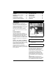
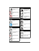
7 4 07800401 2 6 5 KEEP HANDS and FEET AWAY 00 881 029 3 1 2 P 07800403 Figure 2 1. DANGER! 2. DANGER! Discharge Hazard NEVER operate unit without discharge chute in operating position. Thrown objects can cause injury or damage. Discharge Hazard - NEVER direct discharge toward people, pets or property. Thrown objects can cause injury or damage. Do not operate mower unless all guards are in operating position or bagger is attached.
3.2 Discharge Hazard Keep children and others away from unit while unit is in operation. Discharge Hazard - NEVER direct discharge toward people, pets or property. Thrown objects can cause injury or damage. Keep feet and hands away from all rotating or moving parts. Keep children and others away from unit while unit is in operation. DO NOT step or stand in this area. Do not operate mower unless all guards are in operating position or bagger is attached. 3.3 Tipping Hazard 3.
4. DANGER! P Set parking brake. To avoid dismemberment hazard do not put hands near moving belts. Remove key and disconnect spark plug before servicing or making adjustments to unit. Keep hands away from all rotating or moving parts. 3.5 Bystander Hazard DO NOT operate the unit in the presence of bystanders. 5. DANGER! DANGER! Do not carry passengers. ALWAYS Keep hands and feet away from discharge chute. Look behind when operating the unit in reverse.
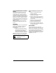
SAFETY RULES 7. CAUTION! The following safety instructions are based on the B71.1 specifications of the American National Standards Institute in effect at the time of production. No smoking. Training IMPORTANT: DO NOT overfill. Fill fuel tank to below bottom of filler neck. WARNING: Overfilling may cause severe damage to evaporative system! • • Never fill fuel tank when engine is running, hot or unit is indoors. Never overfill fuel tank. Replace fuel cap securely and clean up spilled fuel.
Children Tragic accidents can occur if the operator is not alert to the presence of children. Children are often attracted to the machine and the mowing activity. NEVER assume that children will remain where you last saw them. Be alert and turn machine off if a child enters the area. Before and while backing, look behind and down for small children. NEVER carry children, even with the blade(s) shut off. They may fall off and be seriously injured or interfere with safe machine operation.
NEVER direct discharged material toward anyone. Avoid discharging material against a wall or obstruction. Material may ricochet back toward the operator. Stop the blade(s) when crossing gravel surfaces. Use care when approaching blind corners, shrubs, trees or other objects that may obscure vision. NEVER engage PTO when attachment, including mower blades, is not in use. ALWAYS turn off power to attachment when not in active use such as traveling or crossing driveways.
Choose a low ground speed so you will not have to stop or shift while on a slope. DO NOT mow near drop-offs, ditches, or embankments. The machine could suddenly roll over if a wheel goes over the edge or if the edge caves in. DO NOT bypass transmission or allow transmission to free-wheel when on a slope. Fuel To avoid personal injury or property damage, use extreme care in handling gasoline. Gasoline is extremely flammable and the vapors are explosive. Ethanol blends must not exceed E10.
ALWAYS wear safety glasses and protective gear near battery. Use insulated tools. ALWAYS keep batteries out of reach of children. Battery posts, terminals and related accessories contain lead and lead compounds, chemicals known to the state of California to cause cancer and reproductive harm. Wash hands after handling. Transporting Unit Use extra care when loading or unloading the machine into a trailer or truck. Secure unit chassis to transport vehicle.
ASSEMBLY 2 WARNING: AVOID INJURY. Read and understand the entire Safety section before proceeding. Tools Required • • Adjustable wrenches Petroleum jelly or dielectric grease Unpack Unit Remove unit and all other components from the shipping container. Engage transmission bypass lever. See MOVING UNIT MANUALLY on page 20. Push unit from container onto a level surface. Disengage transmission bypass lever. 3 1. Steering Lever 2. Steering Lever Hardware 3.
Check Safety Interlock System WARNING: Safety interlock failure and improper operation of unit can result in death or serious injury. Check system before each use to make sure it is functioning properly. See Safety Interlock System on page 16. Check Function of all Controls See OPERATION on page 16.
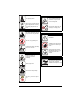
CONTROLS AND FEATURES 6 13 11 8 12 1 2 15 3 5 4 7 10 14 9 Figure 4 1. Ignition Switch 2. PTO Switch 3. Seat 4. Fuel Level 5. Steering Levers 6. Fuel Tank 7. Mower Lift Pedal 8. Mower Deck 9. Discharge Chute 10. Parking Brake Lever 11. Throttle Lever 12. Choke 13. Seat Adjustment Lever (Models 915213, 215) 14. Height of Cut Selector Lever 15.
OPERATION Safety Interlock System WARNING: AVOID INJURY. Read and understand the entire Safety section before proceeding. WARNING: Safety interlock failure and improper operation of unit can result in death or serious injury. Check system before each use to make sure it is functioning properly. CONTROLS AND FEATURES See Figure 4 for all controls and features locations. Perform the following tests to ensure the safety interlock system is working properly.
Steering Levers • • • • Seat Adjustment Reverse (1) – Pull both steering levers backward. Forward (2) – Push both steering levers forward. Left (3) – Pull left steering lever back or push right steering lever forward or a combination of both. Right (4) – Pull right steering lever back or push left steering lever forward or a combination of both. 1 2 3 4 Models 915213, 215 (Figure 6) Push lever back and slide seat forward or backward to the desired position. Release lever to lock seat in position.
NOTE: If water leaks excessively from hose coupling onto top of deck, coupling may not be fully seated onto washout port. Turn off water supply and repeat steps 4 through 6. Use firm pressure while installing coupling onto washout port. 1 3 4 2 WARNING: When using the deck wash system, NEVER engage the deck from any position other than the operator’s seat. DO NOT engage deck in the presence of ANY bystander. 5 1. 2. 3. 4. 5.
IMPORTANT: DO NOT OVERFILL! This equipment and/or its engine may include evaporative emissions control system components, required to meet EPA and/or CARB regulations, that will only function properly when the fuel tank has been filled to the recommended level. Overfilling may cause permanent damage to evaporative emissions control system components. Filling to the recommended level ensures a vapor gap required to allow for fuel expansion.
5. Use steering levers to move the unit. 6. Disengage PTO to stop mower blades. MOVING UNIT MANUALLY (Figure 8) TRANSPORTING UNIT ALWAYS shut off engine, set parking brake, remove key, and properly remove fuel when transporting unit on a truck or trailer. Tie unit down securely. Do not tie down by linkages, guards, cables or other parts that may be damaged. FOR BEST PERFORMANCE Cut grass when it is dry. Keep mower blades sharp. Keep mower deck properly leveled. Do not set height of cut too low.
MAINTENANCE SCHEDULE WARNING: AVOID INJURY. Read and understand the entire Safety section before proceeding. NOTE: To have full access to the engine, the seat must be tipped forward (see TIPPING SEAT FORWARD on page 23) and the hood opened (see OPENING AND CLOSING HOOD on page 23). IMPORTANT: Proper maintenance can prolong the life of unit. The following chart shows the recommended service schedule. Refer to the maintenance instructions in the Engine Manual for additional information.
Interval Task Each Use Follow Engine Manual Maintenance Schedule Action Perform scheduled engine maintenance. Refer to Engine Manual for detailed instructions. NOTE: To drain the oil, remove oil drain cap and attach the oil drain hose, supplied in the lit pack, to the drain plug. Rotate the drain to the left to allow oil to drain. Turn the drain to the right to close. Oil Drain Plug 25 Hours or Every Season Check Battery Lubricate Unit Keep battery and battery terminals clean.
SERVICE AND ADJUSTMENTS MOWER DECK REMOVAL AND INSTALLATION WARNING: AVOID INJURY. Read and understand the entire Safety section before proceeding. Remove (Figure 11) 1. Remove PTO belt from the engine drive pulley. See REPLACING PTO BELT on page 30. 2. Disconnect drag link from the front deck bracket. 3. Disconnect front and rear trunnions from the lift arms on both sides of the unit by removing the 3/8 nuts. Keep hardware for reinstallation. 4. Slide mower deck out from under unit.
7 1 1. 2. 3. 4. 5. 6. 7. Rear Trunnion PTO Belt Mower Deck Drag Link Front Trunnion Lift Arms Nuts 6 2 3 5 7 6 Figure 11 LEVELING AND ADJUSTING PITCH OF MOWER DECK Lowest Cutting Position 1 2 3 Pitch is the difference in blade height from front to back or from side to side. Adjust on a level surface with the tires inflated to the correct air pressure. See Specifications on page 34. Three measurements are required to level and adjust the pitch of the mower deck: 1.
The Forward Pitch Of The Mower Blades Adjusting The Mower Deck To Adjust Mower Blade Height And Pitch (Figure 13) • Front tip of blades should be 0 – 0.635 cm (0 – 1/4") lower than the rear of the blades. NOTE: This measurement must be taken when the mower blade ends point forward. (Figure 15) NOTE: Adjusting the mower deck will adjust the height and pitch of the mower blades. 1. Adjust the trunnions first and re-take the three measurements required to level and adjust the pitch of the mower deck.
REPLACING MOWER BLADE Remove (Figure 16) CAUTION: Mower blades are sharp and can cut you. Wrap the blades or wear gloves, and use extra caution when servicing them. 1. Block mower blades to prevent rotation. 2. Remove mounting hardware and mower blades from spindles. Install (Figure 16) 1. Install mower blades on spindles with mounting hardware. 2. Torque 5/8" nut to 136 to 163 N•m (100 to 120 lb-ft). 2 1 1. Remove mower blade from unit. See REPLACING MOWER BLADE on page 26.
SERVICING THE BATTERY 4. Remove nut and bolt securing battery hold down bracket. Save for reinstallation. NOTE: The bolt securing the battery is mounted through the underside of the frame. Place hand beneath frame to catch loose bolt. 5. Remove battery from unit. NOTE: Unit comes equipped with a maintenance-free battery that requires no regular maintenance except cleaning the terminals.
U1 Battery Installation Cleaning Battery and Battery Cables (Figures 19 and 20) 1. Remove factory battery. See Remove Factory-Installed Battery on page 27. NOTE: Be sure to cut cable tie connecting positive battery cable to battery hold down bracket. 2. Set battery inside the frame, underneath the seat with terminals positioned as shown (Figure 20). 3. Place battery hold down bracket on top of the battery.
ADJUSTING STEERING LEVERS (Figure 21) Rotate this end away from the operator position to move the steering levers in. Adjustment 3 1 Adjustment 1 3 Rotate this end away from the operator position to move the steering levers out. Figure 22 2 3. Adjust Steering Lever Forward or Backward 1. Loosen, do not remove, the bolts securing the handlebar to the upper control arm. 2. Rotate steering lever forward or backward to desired position and tighten bolts. NOTE: Tighten upper bolt first. 6 Adjustment 2 1.
Model 915211 2 3 1 1 1 4 1. Forward Travel Adjustment Bolt 2. Lower Control Arm 2 Figure 23 NOTE: Reverse speed cannot be adjusted. If unit tracks excessively left or right in reverse, see your dealer for repair. REPLACING PTO BELT 1. 2. 3. 4. Remove (Figure 24) 1. Lower mower deck to the ground. 2. Remove belt covers from mower deck. Deck Spindle Engine Drive Pulley Deck Idler PTO Belt Figure 24 Models 915213, 215 2 4 1 1 CAUTION: Use care when releasing idler spring tension.
2. Rotate idler arm clockwise until PTO belt can be routed around left mower deck pulley. 3. Slowly release idler arm until idler pulley rests firmly against PTO belt. 4. Install belt covers on mower deck. NOTE: Ensure that belt is still positioned in the groove of the sheaves after belt covers are installed. STORAGE Short Term Storage REPLACING HYDROSTATIC BELT IMPORTANT: NEVER clean unit with highpressure water or store unit outdoors. Remove all dirt, grease, leaves, etc. Store in a clean dry area.
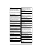
TROUBLESHOOTING PROBLEM Engine will not crank/start. Engine runs rough. Unit does not move with engine running when using steering levers. PTO or mower blades do not engage or shut off. Engine overheats. Unit moves with engine off and parking brake engaged. PROBABLE CAUSE CORRECTION 1. Safety interlock system is not engaged or is faulty. 1. Check safety interlock system. See Safety Interlock System on page 16. 2. Fuel tank is empty. 2. Fill fuel tank. See FILLING FUEL TANK on page 18. 3.
PROBLEM Unit does not travel in a straight line. Unit creeps with steering levers in neutral position. Poor cutting quality. PROBABLE CAUSE CORRECTION 1. Incorrect tire pressure. 1. Check tire pressure. See Specifications on page 34. 2. Steering levers need adjustment. 2. Adjust steering levers. See Forward Speed Adjustment on page 29. 3. Hydrostatic transmission and/or linkage needs adjustment. 3. Contact your Ariens dealer. 1. Hydrostatic transmission and/or linkage needs adjustment. 1.
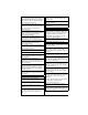
SPECIFICATIONS Model Number Model 915211 915213 915215 Zoom 34 Zoom 42 Zoom 50 Engine Kohler 6000 Type 3 3 660 (40.3) Engine Displacement – cm (in. ) Governed RPM (May be different from maximum RPM) 3600 + 0 / - 100 Drive Forward Max. – km/h (m.p.h) 9.6 (6.0) Reverse Max. – km/h (m.p.h) 4.8 (3.
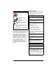
Consumer Mowing Equipment Limited Warranty Warr Ariens Company (Ariens) warrants to the original purchaser that Ariens, Gravely and Countax brand lawn and garden consumer products purchased on or after 9/1/2015 will be free from defects in material and workmanship for the time period noted in the chart below.
• Promptly notify Ariens or an authorized Ariens, Gravely or Countax service representative of the need for warranty service. • Transport the product to and from the place of warranty service at owner's expense. • Have the warranty service performed by an authorized Ariens, Gravely or Countax service representative. To Find an Authorized Service Representative: In the U.S. and Canada: Use the dealer locator on our websites: www.ariens.com • www.gravely.com Or contact us by mail or by phone: In the U.S.
655 West Ryan Street Brillion, WI 54110 ariensstore.com ariens.custhelp.