
Installation Guide

6
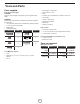
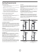
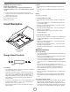
Mark holes
Select the vent option that your installation will require and proceed to
that section:
Outside top exhaust
Use the diagram or the hood as a template and mark the locations on
the cabinet for ductwork, electrical wiring and keyhole screw slots.
35
⁄64”
(1.4 cm)
Wiring access knockout
(cabinet bottom side)
Mounting
screws (4)
6
17
⁄64”
(15.9 cm)
Vent
shims
CENTER
LINE
Cabinet
front side
7
3
⁄32”
(18 cm)
2
19
⁄32”
(6.6 cm)
13
⁄32”
(1 cm)
1
11
⁄16”
(4.3 cm)
10
37
⁄64”
(26.86 cm)
Ø
55
⁄64”
(2.2cm)
1
47
⁄64”
(4.4 cm)
Cabinet bottom side
4
7
⁄32”
(10.7cm)
4
7
⁄32”
(10.7cm)
Vent
system hole
For recessed bottom cabinet only
If the cabinets have front, side or back trim, make 2 wood shims the
width of the trim and attach them to the cabinet bottom recess on
both sides.
Wood shims
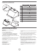
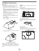
Outside rear exhaust
(Horizontal duct Ø 6” (15.2 cm))
Use the diagram or the hood as a template and mark the locations on
the wall for ductwork, electrical wiring and keyhole screw slots.
4
7
⁄32”
(10.7cm)
1
27
⁄64”
(3.6cm)
4
27
⁄32”
(12.3cm)
4
61
⁄64”
(12.6cm)
9
⁄32”
(0.7cm)
4
7
⁄32”
(10.7cm)
6
17
⁄64”
(15.9cm)
3
25
⁄32”
(9.6cm)
6
57
⁄64”
(17.5cm)
6
57
⁄64”
(17.5cm)
1
11
⁄16”
(4.3cm)
1
1
⁄16”
(2.7cm)
55
⁄64”
(2.2cm)
1
37
⁄64” (4 cm)
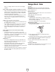
Installation instructions
Ducting version
After having chosen the vent option, proceed as follows:
• Prepare duct and conduit cut outs as needed.
• If possible, disconnect and move freestanding or slide-in
range from cabinet opening to provide easier access to rear
wall.
Otherwise put a thick, protective covering over countertop,
cooktop or range to protect from damage and debris. Select
a at surface for assembling the unit. Cover that surface with
a protective covering and place all canopy hood parts and
hardware in it.
• Determine and mark the centerline on the wall where the
canopy hood will be installed. Select a mounting height co-
fortable for the user and mark on wall.
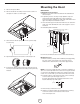
• Prepare duct and conduit cut outs as needed.
• Remove the duct knockouts using a at blade screwdriver
and a small hammer.
• Use the screwdriver by knocking out the pannel in similar
fashion to a scalpel.
• Take care of sharp edges.
A
B
A. Vertical discharge
B. Horizontal discharge
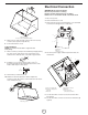
• Attach the 6” round air transition over knockout opening with
2 - 3.5 x 9.5 mm screws.
A
C
C
B
A. 6” round air transition (vertical discharge installation)
B. 6” round air transition (horizontal discharge installation)
C. 2 - 3.5 x 9.5 mm installation screws
NOTE: The exhaust adaptor/damper can be installed up to 1
inch on either side of the hood center to accommodate offcenter
ductwork. In extreme offcenter installations, one end of the duct
connector may need to be trimmed to clear the electrical cable
clamp.