Unvented Hot Water Storage Cylinders Country of destination: GB/IE Instructions for Installation, Servicing and Use LEAVE THESE INSTRUCTIONS WITH THE END-USER
TABLE OF CONTENTS 1. GENERAL INFORMATION 1.1 DELIVERY 2 2. INSTALLATION 2.1 2.2 2.3 2.4 2.5 2.6 2.7 2.8 2.9 2.10 2.11 2.12 WATER REGULATIONS BUILDING REGULATIONS HOW THE APPLIANCE WORKS OVERALL DIMENSIONS COLD WATER SUPPLY SITING AND FIXING CONNECTION OF MAINS WATER SUPPLY COLD WATER COMBINATION VALVE CONNECTION TO SERVICES SECONDARY RETURN DISCHARGE PIPEWORK ELECTRICAL DIAGRAMS 3. COMMISSIONING 4. MAINTENANCE 4.1 4.2 4.3 4.4 4.5 4.
1. GENERAL INFORMATION This manual is an integral and essential part of the product. It should be kept with the appliance so that it can be consulted by the user and our authorised personnel. Please read carefully the instructions and notices about the appliance contained in this manual, as they provide important information regarding the safe installation, use and maintenance of the cylinder. Failure to do so may invalidate the guarantee. 1.
2. INSTALLATION 2.1 WATER REGULATIONS These regulations (byelaws in Scotland) ensure a good supply of wholesome water, and that only approved materials, pipes and fittings are used to convey water. 2.2 BUILDING REGULATIONS These are a statutory document and take priority over all other regulations and recommendations. The installation of an unvented hot water storage cylinder is classified as a “Controlled Service” and Regulation G3 applies.
2.
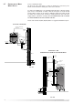
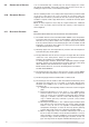
2.7 CONNECTION OF MAINS WATER SUPPLY For floor standing models: On the front of the unit there is a label to identify the connection ports. Please check this before making any connection to the unit. For units up to 300 litres it is recommended that all mains cold water supply pipe work is a minimum of 22mm, with the exception of model ST 50 ProTech where 15mm can be used. For 500 litre models the supply should be 28mm.
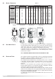
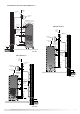
STI/STI PROTECH/ITI 125-150-210-300 INDIRECT COMBINATION VALVE COLD MAINS-IN 22mm EXPANSION VESSEL PRESSURE + TEMPERATURE RELIEF VALVE HOT SUPPLY 22mm 500 STD PROTECH EXPANSION RELIEF PIPE SECONDARY RETURN TUNDISH COLD MAINS-IN 28mm ZONE VALVE COMBINATION VALVE FLOW EXPANSION VESSEL 22mm DRAIN HOT SUPPLY 28mm PRESSURE + TEMPERATURE RELIEF VALVE RETURN MAX. 100mm FIG. 2.
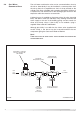
2.8 COLD WATER COMBINATION VALVE The cold water combination valve can be connected either close by the unit or alternatively it may be installed in a remote position from the unit as there is no requirement to site it in close proximity to the cylinder. This allows a flexible and convenient installation. However, it is important to note allowances for the discharge pipe work from the expansion relief valve must be accounted for.
3/4” B.S.P. CONNECTION FOR EXPANSION VESSEL 22mm COLD MAINS IN 3.5 6 BAR SERVICEABLE 3/4” PRESSURE REDUCING CARTRIDGE AND LINE STRAINER (SET AT 3.5 BAR) 22mm TO WATER HEATER 15mm EXPANSION RELIEF OUTLET TO TUNDISH EXPANSION RELIEF VALVE (SET AT 6 BAR) 22mm COLD MAINS IN 22mm TO CYLINDER NON-RETURN VALVE (WITHIN HOUSING) 22mm BALANCED COLD WATER TAKE OFF WITH NON-RETURN VALVE FIG. 2.7 SERVICEABLE 1” PRESSURE REDUCING CARTRIDGE AND LINE STRAINER (SET AT 3.
2.9 CONNECTION TO SERVICES It is recommended that a 22mm pipe run should supply the outlets throughout the building, especially to baths and showers. Short runs of 15mm pipe may be used to connect basins and sinks. 2.10 SECONDARY RETURN On floor-standing models a secondary return may be fitted (consult the label on the face of the unit for the correct location).
connected. If unvented hot water storage systems are installed where discharges from safety devices may not be apparent i.e. in dwellings occupied by the blind, infirm or disabled people, consideration should be given to the installation of an electronically operated device to war n when discharge takes place. Note: The discharge will consist of scalding water and steam.
calculate the next largest size. Maximum resistance allowed for a straight length of 28mm pipe (D2) from G 1/2 temperature & pressure valve equates to: 18m. Subtract the resistance for 4 no. 28mm elbow at 1.0m each = 4m. Therefore the maximum permitted length equates to: 14m As the actual length is 7m, a 28mm (D2) copper pipe will be satisfactory. WARNINGS The outlet from the temperature & pressure relief valve must not be used for any other purpose. This also applies to the expansion relief valve.
prevent risk to the appliance’s lifespan when disconnecting the protection system for an extended period of time, it is necessary to drain the appliance beforehand. In addition to the 240V network, the electronic circuit is also connected to the tank, which is to be protected, and to the titanium protection electrode, INFORMATION FOR THE END USER Proper operation of the protection system is shown by a continuous green L.E.D, indicating that the circuits terminals are being supplied with electricity.
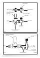
2.11 ELECTRICAL DIAGRAM Should the Economy 7 system not to be used, a separate 13 amp supply to each element will be required. Through a double pole fused isolating switch having a contact gap of at least 3mm on each pole.The immersion heater shall be installed with 85°C rubber insulated HOFR-sheathed flexible cable complying with Table 8 of BS 6141: 1991. Make the connection(s) to the immersion heater(s) as per FIG. 2.12 and FIG. 2.13.
FIG. 2.
BASIC BOILER LIST Baxi Bermuda range Boston RS and OF range Glowworm Complheat Hideaway range Ultimate 65 - 80 40 - 80 30B - 80B, 30CF - 60CF Halstead Buckingham range Potterton Kingfisher range Statesman range (oil fired) Caradon Ideal Classic range Mexico Super range Mexico Slimline range Newflame Boilers Backboiler range Condensing Boiler List CARADON IDEAL GLOWWORM KESTON POTTERTON Minimiser FF30 - FF80 Energysaver (Remove link SL-9) L Envoy 30F - 80F VAILLANT VU 186, 226 Boiler Connect
3. COMMISSIONING Check for obvious signs of damage to the cylinder and controls, and also that the controls fitted correspond with the references quoted in these instructions. Ensure that the Drain Cock at the base of the appliance is closed before commencing. 1) ProTech Models Only.
4. MAINTENANCE To ensure efficient safe operation, it is recommended that the appliance is serviced annually by a competent person. After servicing, preliminary electrical system checks must be carried out to ensure electrical safety (i.e. polarity, earth continuity, resistance to earth and short circuit). 4.1 PROTECH ANTI-CORROSION SYSTEM WARNING: SWITCH OFF THE POWER SUPPLY BEFORE WORKING ON THE APPLIANCE. Trouble-shooting: 1) The green L.E.D.
4) Expansion relief valve - check manually by turning the test knob (ensure valve closes after testing); 5) Discharge pipes (D1) - from both temperature & pressure relief and expansion relief valve for obstructions; 6) Tundish & discharge pipe (D2) - open either valve gradually to produce a full bore discharge into tundish and D2 without any back pressure; 7) Pressure reducing valve - check that the correct outlet pressure is being maintained by recording the pressure at an in-line terminal fitting i.e.
Unvented Controls(s) Check controls as per the following: 1) Line strainer - with the water supply turned off remove screen from strainer and clean of any detritus; 2) Expansion vessel - with the water supply turned off and taps open, check expansion vessel pressure and top up as necessary; 3) Temperature & pressure relief valve - with the water supply turned on, check manually by lifting the test lever/turning the test knob (ensure valve closes after testing); 4) Expansion relief valve - check manually by
5. FAULT FINDING FAULT POSSIBLE CAUSES REMEDY 1) Mains cold water supply shut off Check and open Isolating and/or stop valve.
Kg mins bar kW m2 mins bar bar bar bar bar/°C bar V kW mm ST ProTech 50 12 3.5 3.5 6 7/90 3.5 240 3 480 (1) (3) 60 1.15 27 ST ProTech 80 12 3.5 3.5 6 7/90 3.5 240 3 480 (1) (3) 90 1.40 40 ST ProTech 100 12 3.5 3.5 6 7/90 3.5 240 3 480 (1) (3) 120 1.26 41 12 3.5 3.5 6 7/90 3.5 240 3 350 (1) (3) 120 1.50 29 STD ProTech 100 STD/STD ProTech 125 STD/STD ProTech 150 12 3.5 3.5 6 7/90 3.5 240 3+3 350 (1) (3) 240 2.10 45 STD/STD ProTech 300 12 3.5 3.5 6 7/90 3.5 240 3+3 350 (1) (3) 350 2.
NOTES 23
MTS Benelux sa/nv - Belgium Commercial subsidiary: MTS (GB) LIMITED MTS Building Hughenden Avenue High Wycombe Bucks. HP13 5FT Telephone: (01494) 755600 Fax: (01494) 459775 Internet: www.ariston.co.uk E-mail: info@uk.mtsgroup.