
Instructions / Assembly

lp-772 Rev. 000 Rel. 000 Date 3.17.21
9
• Make certain that the drain valve is completely closed.
• Open the shut-o valve in the cold water supply line.
• Open the hot water faucets to allow air to vent from the heater and piping.
• Allow sucient time for the heater to completely ll with water.
• Verify the element is installed correctly. Check for leaks.
H. Filling the Heater
When lling the water heater, open a hot water tap to release air in the tank and piping. The tank must be full of water before the heater
is turned on. Failure to ensure the water heater is full before turning it on could result in damage to the water heater and other property
damages. Such damages ARE NOT covered by water heater warranty.
CAUTION
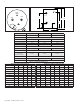
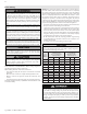
Table 1 details the relationship of water temperature and time with regard to scald injury and may be used as a guide in determining the safest
water temperature for your applications.
I. Applications
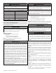
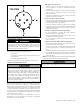
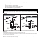
TOP OPTION INSTALLATION
Figure 4 - Piping Details - NOTE: Drawings are meant to demonstrate system piping concept. Heat traps are optional but recommended.
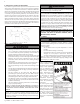
PIPING NOTES:
The following notes are applicable to all of the piping applications demonstrated on this page.
1. Minimum pipe size should match connection size. Upsize pipe accordingly if greater ow is required.
2. A thermal expansion tank suitable for potable water must be sized and installed within this piping system between the backow preventer and the cold
water inlet.
3. All circulators should have an integral ow check.
4. Drains and check valve between unit and storage tank will assist in purging air from system.
5. These drawings are meant to demonstrate system piping only. The installer is responsible for all equipment and detailing required by local codes. In
Massachusetts, you must install a vacuum relief valve per 248 CMR.
6. Mixing valve application is optional, but recommended to help prevent scalding. See Part 3 for more information.