SYSTEM A System A 24 RFFI System A 30 RFFI Installation and Servicing Instructions Type C Boilers G.C.N: G.C.
These instructions are suitable for the System A boilers : MTS supports Benchmark, the heating industry code to ensure the correct installation, commissioning and servicing of domestic central heating systems. To The Householder Make sure that your installer completes Section 24 of this manual, this provides a record of the commissioning of your boiler. It contains important information about your particular installation that may be required by service engineers.
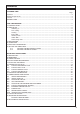
Contents CUSTOMER CARE Page Guarantee ............................................................................................................................................................2 Statutory Requirements .......................................................................................................................................2 Contents ...................................................................................................................................................
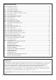
SERVICING INSTRUCTIONS 18 REPLACEMENT OF PARTS .........................................................................................................................45 18.1 To Gain General Access........................................................................................................................45 18.1.1 Removing the front panel.......................................................................................................................45 18.1.2 Lowering the control panel.....
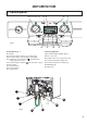
USER’S INSTRUCTIONS 1. Control panel 27 26 30 (System Plus only) 29 31 Fig 1 32 Control panel (fig. 1) 31.- Central Heating start button 32.- Menu button 33.- Reducing button 34.- Increasing button 35.- Setting button 34 35 Connecting bracket Taps shown in Open position (fig. 2) 26.- Display 27.- On/off push button and power on indicator light 29.- Reset push button and red indicator locking light 30.
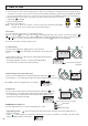
2. How to Use Switching on and filling instructions 1. Check the pressure in the central heating system is above 0.7 bar and below 1.5 bar with the pressure gauge 16 (fig.1), should it be neccessary to re-pressurise the system,ensure the filling loop 45 (fig. 2) is attached, open the filling taps 43 & 44, the pressure gauge will now start to rise, once the pressure reads 1.0 bar, close the filling taps and disconnect the filling loop. 2.
Anti-freeze and anti-sieze modes Provided the ON/OFF button is on (green light), the water pressure is adequate and the boiler has not shut down due to an error, the anti-freeze and ant-sieze operations will remain active. . When the anti-freeze comes on, one of two codes will be displayed with the snowflake pictogram The two possible codes are 05 (pump anti-freeze) or 06 (burner anti-freeze).
6. Setting the time clock 6.1 Setting the mechanical clock 12 9 3 6 Fig. 3 A 3 2 4 1 24 23 22 12 5 21 C 6 7 19 9 20 I 8 18 9 17 B 15 14 13 10 16 6 12 11 Fig. 4 1. General layout The mechanical clock covers a 24 hour period. Each tappet represents 15 minutes A (Fig. 4). An override switch is located on the clock B (Fig 4). 2.
6. Setting the time clock (continued) 6.2 Setting the Digital Clock Manual switch Summer and winter time setting Reset Enter switching times h Prog . Enter the hours Weekdays flash m Imput time Enter minutes Day Enter weekday/s Automatic Operation Manual Operation Continuous Operation = ON = ON = Continuously ON = OFF = OFF = Continuously OFF The switching times correspond to the program entered.
6. Setting the time clock (continued) Entering the switching times You have 20 memory Iocations available. Each switching time takes up one memory location. Keep pressing the “Prog” button until a free memory location is shown in the display “– –:– –”.
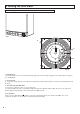
INSTALLER’S INSTRUCTIONS 7. Description 1.- Steel chassis complete with expansion vessel 2.- Sealed chamber 3.- Burner and heat exchanger assembly 4.- Air / gas connection 5.- 24 V modulating fan 6.- Gas valve 7.- Ignition electrode 8.- Ionisation probe 9.- Ignitor 10.- Combustion products manifold 11.- Siphon 12.- Silencer 13.- Electrical box 14.- Pump 16.- Pressure gauge 17.- Three way valve 18.- Automatic air separator and automatic vent 20.- Main exchanger inlet thermistor 21.
8. Dimensions All dimensions in mm 289 21 Safety valve C/H and condensate Heating flow K Cylinder return (System Plus only) L Gas supply M Cold water supply N Heating return With packaging : 24 kW : 34 kg 30 kW : 37 kg 691,5 720 162 141 I J 172,5 121,5 4,7 I J KLM N I minimum space required 450 450 mini pour entretien 32 296 296 (24 kW) 360 (30 kW) 440 390 54 54 54 54 J K L M N Fig. 8 9. Hydraulic data The boiler is fitted with an automatic by-pass as standard.
10. Installation Requirements Reference Standards In the United Kingdom, the installation and initial start up of the boiler must be by a CORGI Registered installer in accordance with the installation standards currently in effect, as well as with any and all local health and safety standards i.e. CORGI. In the Republic of Ireland the installation and initial start up of the appliance must be carried out by a Competent Person in accordance with the current edition of I.S.
10. Installation Requirements (continued) It must also be possible to be able to completely isolate the appliance electrically. Connection should be via a 3 amp fused double-pole isolating switch with a contact separation of at least 3 mm on both poles. Alternatively, a fused 3 Amp. 3 pin plug and unswitched socket may be used, provided it is not used in a room containing a bath or shower. It should only supply the appliance. The boiler is suitable for sealed systems only.
10. Installation Requirements (continued) iii) Terminating into a gully, below the grid level but above the water level. iv) Into a soakaway. fall. The total length of external pipe used should not exceed 3 metres. Some examples of the type of condensate terminations can be found below. NOTE: If any condensate pipework is to be installed externally then it should be kept to a minimum and be insulated with a waterproof insulation and have a continuous 1. 2.
10. Installation Requirements (continued) 3. External termination of condensate drainage pipe via internal discharge branch (e.g. sink waste - proprietary fitting) 4.
11. Installing the Boiler Please check that you are familiar with the installation requirements before commencing work (Section 10).
11. Installing the Boiler (continued) A A Fig. 12 1 2 Fig. 13 P P Fig. 14 Fig.
12. Connecting the Flue The boiler should only be installed with a flue system supplied by MTS (GB) Limited. These kits are supplied separately to the appliance in order to respond to different installation solutions. For more information with regard to the inlet/outlet accessories consult the accessory catalogue. The boiler is supplied ready for connection to a concentric flue system.
12.1 Fitting the coaxial flue (Ø 60/100 Horizontal) CONTENTS: 1X SILICONE O-RING (60mm) 1X ELBOW (90 ) 2X WALL SEALS (INTERNAL & EXTERNAL) 1X FLUE PIPE INCLUDING TERMINAL (1 METRE - 60/100) 1X FLUE CLAMP 1X SCREWS 1x Seal Once the boiler has been positioned on the wall, insert the elbow into the socket and rotate to the required position. possible to rotate the elbow 360o on its vertical axis. O NOTE: It is Using the flue clamp, seals and screws supplied (Fig 19) secure the elbow to the boiler.
162 Fig. 20 Fig. 21 Fig.
12.3 Fitting the Coaxial Flue (Ø 60 / 100 Vertical) NOTE: SEE PAGE 24 FOR MAXIMUM AND MINIMUM FLUE RUNS. CONTENTS: 1X SILICONE O-RING (60mm) 1X CONICAL ADAPTOR (60/100mm) 1X VERTICAL FLUE KIT (80/125mm) 3X SCREWS The vertical flue kit is supplied with a specially designed weather proof terminal fitted, it can be used either with a flat roof or a pitched roof. The Vertical flue kits useable lengths with the pitched roof flashings are indicated in Fig. 23.
12. Connecting the flue (continued) 12.4 Fitting the twin pipe (Ø80/80) NOTE: SEE PAGE 24 FOR MAXIMUM AND MINIMUM FLUE RUNS (TABLE C) Where it is not possible to terminate the flue within the distance permitted for coaxial flues, the twin flue pipe can be used by fitting a special adaptor to the flue connector and using the aperture for the air intake located on top of the combustion chamber. Always ensure that the flue is adequately supported, avoiding low points. (MTS supply suitable clamps as Part No.
12.4 Fitting the twin pipe flue (Ø80/80) (continued) ø 100 123,5 107 200 25 Fig. 27 60 mm Fig. 28 In the event that twin flue pipes are used, and the boiler has a side clearance of less than 60mm from the wall, it is necessary to cut a larger diameter hole for the flue pipe, this should be ø10 cm, this will then allow for easier assembly of the air intake elbow and the tube outside the wall (see Fig. 28).
12.4 Fitting the twin pipe flue (Ø80/80) (continued) TYPE 1 TYPE 4 TYPE 3 TYPE 2 TYPE 5 NOTE: DRAWINGS ARE INDICATIVE OF FLUEING OPTIONS ONLY. AIR INTAKE MUST NOT BE FITTED ABOVE THE EXHAUST AIR INTAKE EXHAUST AIR INTAKE Fig.
13. Electrical connections Making the Electrical Connections Hinge down the electrical box to gain access to the electrical connections. Push in the tabs P (Fig. 30) on either side of the boiler and pivot the box forward. Remove the PCB cover (see Section 18.4). Connect the live neutral and earth wires to the main cable. P If using a room thermostat or other external control, they can be connected in place of the link on the terminal block (Diagram A- Fig. 32).
4 LEGEND 1 1 2 3 4 5 6 7 8 9 10 11 12 13 14 15 3 2 15 NTC Connectors Display Connectors EEPROM Button 24V DC Supply Fan Connector Flame Detection Connector Fuses 2A 230V (X2) 230V Connector Auxillary 230V Connector Actuators 230V Connector Time Clock Connector (Internal) Room Thermostat Connector Remote Control Connector Under Floor Heating Connector Not Used Fig.
13. Electrical connections (continued) 13.1 Fitting the mechanical and digital time clocks To fit the integral time clock it is necessary to proceed as follows; - Isolate the electical supply to the appliance; Remove the front panel as described in Section 18.1.1; Remove the plastic cover on the right hand side (Fig. 33) and pull out the 4 wires (Fig. 34); Connect the time clock wires as follows; MECHANICAL MODEL (Fig.
13. Electrical Connections (continued) 13.2 Connecting Zone Valves (System A) The boiler can be connected to a central heating system that uses two zone valves to allow connection to an indirect storage cylinder. There are two wiring diagrams shown, one for the connection to an Unvented Cylinder (Diagram. A) and one for connection to an open vented cylinder (Diagram B). In both cases the boiler connection is shown as ROOM , which relates to the terminal on the PCB for external controls (see 12 FIG. 31).
WIRING DIAGRAM FOR CONNECTION TO AN OPEN VENTED CYLINDER 30 DIAGRAM B
WIRING DIAGRAM FOR CONNECTION TO AN MTS UNVENTED CYLINDER DIAGRAM A 31
14. Commissioning and Testing 14.1 Initial preparation MTS (GB) Limited support the initiative. In Sections 24 and 25 (pages 60 and 61) of this manual the Commissioning Checklist and Service Interval Record can be found. It is important that this is completed in the presence of your customer, they are shown how to use it, and it is signed by them. Please instruct your customer that they must have this manual with them whenever they contact a service engineer or us.
14. Commissioning and testing (continued) 14.3 Adjusting the CO2 14.4 Gas Conversion 2. Make sure that all radiator valves are open; 3. Turn on the gas cock and check the seals on the connections with any approved soap solution and eliminate any leaks; 4. Press the reset button 29 (Fig. 1) the boiler will re-attempt ignition. If the burner does not light the first time, wait 1 minute and repeat the procedure; 5.
14.7 External sensor and ambient sensor set-up (where fitted) N.B. To ensure that these parameters are set correctly, consult the "thermo-regulation help" document enclosed with the documentation folder. 14.8 Completion For the Republic of Ireland it is necessary to complete a “Declaration of Conformity” to indicate compliance to I.S.813. An example of this is given in the current edition of I.S.813. In addition it is necessary to complete the Commissioning Checklist in Section 24 of this manual (Page 60).
14. Commissioning and testing (continued) 14.10 Instructing the end user 1. Hand over these instructions and explain how to use the time clock and room thermostat (if fitted) and explain how to register the guarantee; 2. Show the end user how to switch the appliance off quickly, and indicate the position of the electric supply isolator; 3. Inform the end user of the location of all drains, isolating valves and air vents; 4.
15. Fitting the casing Fitting the casing Remove the protective film on the casing: - Locate the lower clips into the slots in the chassis - Engage hooks N on the casing in notches R on the side panels M operation (Fig. 43) - Fit the top of the panel in place - Close the panel mounting clamps (Fig. 44) - Screw in the two clamp locking bolts A Note: it is essential to refit both locking bolts A A M 1 R Fig. 44 Fig.
16. Sequence of operation Central Heating Mode Activation of the time clock and/or room thermostat starts the boiler. The display panel indicates the flow temperature s in central heating as illustrated below: Central heating mode ON Room thermostat contact ON With the boiler in rest, the diverter valve is in the domestic hot water position, activation of the central heating changes the position of the motorised valve head, moving the diverter valve into the central heating position.
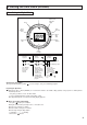
17. Adjustments and settings 24 23 5 6 I 7 19 9 8 18 9 17 15 14 13 10 12 11 + button 16 6 P Reset push button - button 20 DISPLAY 1 12 21 On/Off push button Menu button 2 4 3 22 The boiler is delivered with pre-set values described in menus 3 and 4. All settings must only be changed by the installer or a qualified person. To gain access to the setting buttons please, open the front control panel cover P) and follow the instructions below.
ACTION DISPLAY CONFIGURATION Menu - 1 - Default register Record the last 10 defaults 5” Digit 1 Digit 2 Digit 3 and 4 Last default occured 1 0 code from 01 to 99 Last but one default occurred 1 1 code from 01 to 99 ... 1 ...
DISPLAY CONFIGURATION Factory setting ACTION Menu - 3 - Boiler options once Rubrique x times Elément 1 Elément 2 Inactive 3 0 DHW thermostatic kit fitted to boiler? (fix DHW temp to 65°C) 3 1 Elément 3 et 4 -- 0 : non 1 : oui 0: on heating and reheating of tank Optional programmer action 3 2 1: on reheating of tank 2: on the heating Inactive 3 3 -- Inactive 3 4 -- 3 5 0 to 5 mn by step 0,5 mn 3 7 -- DHW Delay (time before CH relight after a DHW cycle) Inactive 40
DISPLAY CONFIGURATION Factory setting ACTION Menu - 4 - Boiler settings once Section Digit 1 Digit 2 4 0 Digit 3 and 4 0 : no Stop pump after burner stops 1 : yes x times 0 : High speed Pump speed 4 1 1 : Adaptive 0 to 5 min by step 0.5 min Pump post circulation duration 4 2 Inactive 4 3 Maximum Central Heating flow temperature 4 4 Minimum Central Heating flow temperature 4 5 Inactive 4 6 Inactive 4 7 CH anti-cycling delay 4 8 0 to 7 min by step 0.
ACTION DISPLAY CONFIGURATION Menu - 5 - Combustion rate control mode Effect Display once Combustion rate control mode OFF Combustion rate control mode ON The main exchanger temperature appears on the display. The digit - on the display shows the gas output level. (Top = maxi, bottom = mini). Gaz output setting To modify the gas output use + and buttons. once x times To cancel the combustion rate control mode press button “Menu”.
DISPLAY CONFIGURATION Factory setting ACTION Menu - 6 - Thermo-regulation settings once Section Digit 1 Digit 2 Digit 3 and 4 0: Heating setting can be adjusted by the user 1: Variable heating setting depending on the external temperature x times Type of control 6 0 2: Variable heating setting depending on the room temperature (Clima Manager)* 3: Variable heating setting depending on the external and room temperatures (Clima Manager)* Compensation 6 1 If or 00 to 20 in intervals of 1 Slo
17. Adjustements and Setting (continued) CH anti cycling delay setting : If you would like to change the setting of CH anti cycling delay, if you want 3 mn ,please proceed as follow : (note : the factory setting is 2 mn 30 seconds and the following explanation refer to menu 4 section 8) Display 1 Switch to installer mode, press button and 1 5” for 5 seconds, the display shows :10=0 if there is no default in the default register.
SERVICING INSTRUCTIONS A To ensure efficient safe operation, it is recommended that the boiler is serviced annually by a competent person, refer to Section 20 (page 53) for the Servicing Schedule. Before starting any servicing work, ensure both the gas and electrical supplies to the boiler are isolated and the boiler is cool. Before and after servicing, a combustion analysis should be made via the flue sampling point.
18.2 Access to the Combustion Chamber 18.2.1 Removing the air gas assembly 1. Isolate the gas supply to the boiler; 2. Carry out step 18.1.1; 3. Remove the silencer (Fig. 49); 4. Disconnect the detection electrode cable (Fig. 50); 5. Remove the earth cable from the ignition electrode (Fig. 51), and remove the ignition electrode cable from the ignitor (Fig. 52) Fig. 51 Fig. 50 Fig. 49 6. Unplug the gas valve and fan connectors (Figs. 53 and 54); Fig. 52 Fig. 54 Fig. 53 7.
18.2.2 Removing the burner Do not remove the burner unless absoluly necessary. 1. Carry out step 18.1.1 and 18.2.1 (without removing the 4 nuts D); 2. Remove the 3 screws F from the air/gas manifold (Fig. 58); 3. Slide the burner out from the front, taking care not to damage the insulation (Fig. 59a 24 kW & 59b 30 kW); 4. Reassemble in reverse order and checking all seals are undamaged and the burner is positioned correctly (Fig. 60). If necessary, replace the insulation too. D Fig. 59a F Fig.
18.2.5 Removing the fan 1. Carry out step 18.1.1; 2. Remove the air gas manifiold as in step 18.2.1 (Fig. 67); 3. Unscrew the two screws from the venturi J and remove with the gas valve (Fig. 68); 4. Unscrew the three screws K on the air/gas pipe and remove (Fig. 69); 5. Reassemble in reverse order. K J Fig. 67 Fig. 68 Fig. 69 18.2.6 Removing the gas valve 1. Carry out step 18.1.1; 2. Remove the air gas manifiold as in 18.2.1 (Fig. 70); 3.
18.2.7 Removing the heat exchanger 1. Carry out step 18.1.1; 2. Remove the air gas manifiold as in 18.2.1 (Fig. 74); 3. Remove the flow pipe clip and unscrew the pump nut (Fig. 75a & 75b); 4. Remove the flow and return pipes and the condense drain pipe from the heat exchanger. (Fig. 75c); Fig. 75a Fig. 74 Fig. 75b 5. Remove the two bolts securing the exchanger (Fig. 76); 6. Remove the screw M2; then rotate clockwise the bearing frame (Fig. 77); Fig. 75c 7.
18.3 Access to the Water Circuit Important! Before any component is removed, the boiler must be drained of all water. 18.3.1 Drain down Close the flow and return isolating valve and open the pressure relief valve. 18.3.2 Removing the 3 way valve 1. 2. 3. 4. 5. 6. Carry out step 1.2.1 and 1.2.3; Remove the clip “Q1” from the by-pass tube (see fig. 87); Remove the clip “Q2” and “Q3” from the heating return and the pump (see fig. 88 & 89); Remove the two T25 screws “P1” (see fig.
18.3.5 Removing the pump 1. Carry out step 18.1.1; 2. Lower the electrical box cover as in step 18.1.2; 3. Remove the PCB cover; 4. Remove the pump plug from the control board and earth plug from earth socket (see Fig. 93); 4. Unscrew the pump nut (see Fig. 94); Fig. 93 5. Remove the clip S2 on the pump volute (see Fig. 95); Fig. 94 6. Pull the pump toward you and remove the clip S3 securing the pressure gauge (see Fig. 96); 7. Reassemble in reverse order. S2 S3 Fig. 96 Fig. 95 18.3.
18.3.7 Removing the expansion vessel 1. Carry out step 18.3.1; 2. Isolate the gas supply and disconnect all pipe connections; 3. Remove the boiler from the wall 4. Unscrew the nut U (see Fig. 98); 5. Pull the expansion vessel to remove it (see Fig. 99); 6. Reassemble in reverse order. U Fig. 98 18.3.8 Removing the overheat thermostat 18.3.9 Removing the temperature sensors (N.T.C’s) 1. Remove the casing as in step 18.1.1; 2. Pull off the thermostat connections.
18.3.10 Removing the pressure gauge 18.3.11 Removing the water pressure switch 1. Carry out step 18.4.6; 2. Remove the pressure gauge by releasing the two clips V and pulling the pressure gauge out. (see Fig. 102) 1. Remove the casing as in step 18.1.1; 2. Pull off the connections. Then remove the pressure switch by releasing it’s securing clip (see Fig. 103). V Fig. 102 Fig. 103 18.3.12 Removing & cleaning the condensate trap 1. Unscrew the cap of the condensate trap (see Fig. 104) 2.
4. Remove the two screws W3 from the front control panel and lower the front control panel (see Fig. 108); 5. Remove all electrical connections from the display PCB (see Fig. 109; W3 Fig. 108 6. To remove the display PCB, remove the two screw W3 and lift the PCB out (see Fig. 110); 7. Reassemble in reverse order; Fig. 109 8. To remove the main PCB disconnect all electrical connections and remove the two screws W5 (see Fig.
19. Incorrect function In case of problem, or when the boiler has displayed an error code, the display flashes 2 digits. Please refer to the table below to diagnose the fault. For faults 01 and 03, A appears on the display, the boiler is locked and the reset button illuminates (28). To reset the boiler press the reset button 29. 29 Overheating lock out FAULT Fig.
20. Gas conversion If the boiler is not set for the gas type, converson kits are available. To convert the boiler, please use exclusively MTS parts and proceed as it is mentioned in the instruction manual provided with the conversion kit. 21.
22. Maintenance Instructions 22.1 General remarks 22.2 Cleaning the primary exchanger It is recommended that the following inspections be carried out on the boiler at least once a year; Cleaning the exhaust side 1. Check the seals in the water group, and if necessary, replace the gasket and restore the seal to perfect working order; Remove the air gas assembly (Section 18.2.1).
23. Short spares list 103 539 101 543 615 110 112 624 502 111 506 616 554 531 649 401 532 537 538 407 Key N Description Manf. Pt. N Type Other SY ST EM A 24 30 FF FF 0100 0101 BURNER ASSEMBLY BURNER 24KW BURNER 30KW 0103 0110 0111 0112 SOUPAPE 0400 0401 GAS SECTION IGNITION ELECTRODE IONIZATION ELECTRODE GASKET D:85-66.5-2.
24.
25. Benchmark Commissioning Checklist BENCHMARK No. GAS BOILER COMMISSIONING CHECKLIST BOILER SERIAL No. NOTIFICATION No.
26. Service Interval Record S E R V I C E I N T E R VA L R E C O R D It is recommended that your heating system is serviced regularly and that you complete the appropriate Service Interval Record Below. Service Provider. Before completing the appropriate Service Interval Record below, please ensure you have carried out the service as described in the boiler manufacturer’s instructions.
TERMS AND CONDITIONS OF GUARANTEE Please read these terms and conditions which are in addition to any terms and conditions detailed in this book or any registration card supplied with your appliance. A charge will be made to the owner of the appliance if: ∑ ∑ ∑ ∑ The reason for any service visit is as a direct result of a failure to install the appliance in accordance with the manufacturer’s instructions.
Chaffoteaux & Maury are continuously improving their products and therefore reserve the right to change specifications without prior notice and accepts no liability for any errors or omission in the information contained in this document. 64 MTS (SA) - France Commercial subsidiary: MTS (GB) Limited MTS Building Hughenden Avenue High Wycombe Bucks HP13 5FT Telephone: (01494) 755600 Fax: (01494) 459775 internet: www.mtsgb.itd.uk E-mail: info@mtsgroup.