Installation and Servicing Instructions Type C Boilers microGENUS HE 24 MFFI G.C.N: 47-116-37 microGENUS HE 28 MFFI G.C.N: 47-116-38 microGENUS HE 32 MFFI G.C.
TABLE OF CONTENTS 1. GENERAL INFORMATION 1.1 1.2 2. GENERAL INSTRUCTIONS OVERALL VIEW INSTALLATION 2.1 2.2 2.3 2.4 2.5 2.6 2.7 2.8 2.9 2.10 2.11 2.12 2.13 2.14 2.15 2.16 2.17 2.18 3.
1. GENERAL INFORMATION This manual is an integral and essential part of the product. It should be kept with the appliance so that it can be consulted by the user and our authorised personnel. Please carefully read the instructions and notices about the unit contained in this manual, as they provide important information regarding the safe installation, use and maintenance of the product. For operating instructions please consult the separate End User Manual. 1.
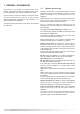
1.2 OVERALL VIEW LEGEND: 1 28 2 27 3 26 4 5 25 6 7 8 24 9 10 11 12 13 14 23 22 21 20 15 16 17 18 19 FIG. 1.0 4 1. 2. 3. 4. 5. 6. 7. 8. 9. 10. 11. 12. 13. 14. 15. 16. 17. 18. 19. 20. 21. 22. 23. 24. 25. 26. 27. 28.
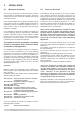
2. INSTALLATION 2.1 REFERENCE STANDARDS The technical information and instructions provided herein below are intended for the installer / Servicing Technician so that the unit may be installed and serviced correctly and safely. In the United Kingdom the installation and initial start up of the boiler must be by a CORGI Registered Installer in accordance with the installation standards currently in effect, as well as with any and all local health and safety standards i.e. CORGI.
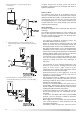
2.3 OVERALL DIMENSIONS LEGEND: A = Central Heating Flow (3/4” - 22mm Copper Tail) B = Domestic Hot Water Outlet (1/2” - 15mm Copper Tail) C = Gas Inlet (3/4” - 15mm Copper Tail) D = Domestic Cold Water Inlet (1/2” - 15mm Copper Tail) E = Central Heating Return (3/4” - 22mm Copper Tail) 120 FIG. 2.1 2.4 CLEARANCES In order to allow access to the interior of the boiler for maintenance purposes, the boiler must be installed in compliance with the minimum clearances indicated in FIG. 2.2 FIG. 2.2 2.
Gas Engineers document REF: IGE/UP/7. 2.5.1. Drill the wall and plug using those supplied with the connections kit, position the hanging bracket and secure with the wall bolts supplied, assemble the connection kit and secure to the wall. NOTE: It is highly recommended that a spirit level be used to position the appliance to ensure that it is perfectly level. 2.5.2. Position the appliance on the hanging bracket and connect the connection kit to the boiler connections. (see also Sections 2.
2.7 GAS CONNECTION The local gas region contractor connects the gas meter to the service pipe. If the gas supply for the boiler serves other appliances ensure that an adequate supply is available both to the boiler and the other appliances when they are in use at the same time. Pipe work must be of an adequate size. Pipes of a smaller size than the boiler inlet connection should not be used. 2.
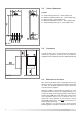
SAFETY VALVE DISCHARGE: The discharge should terminate facing downward on the exterior of the building in a position where discharging (possibly boiling water & steam) will not create danger or nuisance, but in an easily visible position, and not cause damage to electrical components and wiring. The discharge must not be over an entrance or a window or any other type of public access.
1. Internal termination of condensate drainage pipe to internal stack E C I 2 2 6 5 6 1 4 5 4 1 3 3 frequent filling of the heating system can lead to premature scaling of the main exchanger and failure of hydraulic components. DOMESTIC WATER: The domestic water must be in accordance with the relevant recommendation of BS 5546:1990.
4. External termination of condensate drainage pipe via condensate siphon mixture of the boiler circuit and replace it when the amount measured is out of the range stipulated by the manufacturer ( 7 < pH < 8). DO NOT MIX DIFFERENT TYPES OF ANTI-FREEZE - In under-floor systems, the use of plastic pipes without protection against penetration of oxygen through the walls can cause corrosion of the system’s metal parts ( metal piping, boiler, etc), through the formation of oxides and bacterial agents.
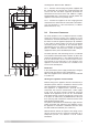
2.9. CONNECTING THE FLUE IMPORTANT!! BEFORE CONNECTING THE FLUE, ENSURE THAT 1 LITRE OF WATER HAS BEEN POURED INTO THE EXHAUST CONNECTION TO FILL THE CONDENSATE TRAP (FIG.2.7). SHOULD THE TRAP BE EMPTY THERE IS A TEMPORARY RISK OF FLUE GASSES ESCAPING INTO THE ROOM. FLUE SYSTEM The provision for satisfactory flue termination must be made as described in BS 5440-1. The appliance must be installed so that the flue terminal is exposed to outdoor air.
Warning The exhaust gas ducts must not be in contact with or close to inflammable material and must not pass through building structures or walls made of inflammable material. When replacing an old appliance, the flue system must be changed. Important Ensure that the flue is not blocked. Ensure that the flue is supported and assembled in accordance with these instructions. Level 118 Installation without extension 150 mm FIG. 2.
Clamp Screws FIG. 2.12 Seal Should the flue require extending, the flue connections are push fit, however, one flue bracket should be used to secure each metre of flue. 2.9.2 FITTING THE 5” FLUE (Ø 80 / 125 HORIZONTAL / VERTICAL) NOTE: SEE PAGE 19 FOR MAXIMUM AND MINIMUM FLUE RUNS. Once the boiler has been positioned on the wall, it is necessary to insert the Ø80/125 adaptor (FIG. 2.
NOTE: SEE PAGE 19 FOR MAXIMUM AND MINIMUM FLUE RUNS. 2.9.3. FITTING THE COAXIAL FLUE (Ø 60 / 100 VERTICAL) CONTENTS: 1X SILICONE O-RING (60mm) 1X CONICAL ADAPTOR (60/100mm) 1X VERTICAL FLUE KIT (80/125mm) 3X SCREWS The vertical flue kit is supplied with a specially designed weather proof terminal fitted, it can be used either with a flat roof or a pitched roof. The Vertical flue kits useable lengths with the pitched roof flashings are indicated in Fig. 2.15.
2.9.4. FITTING THE TWIN PIPE (Ø80 / 80) NOTE: SEE PAGE 19 FOR MAXIMUM AND MINIMUM FLUE RUNS. Where it is not possible to terminate the flue within the distance permitted for coaxial flues, the twin flue pipe can be used by fitting a special adaptor to the flue connector and using the aperture for the air intake located on top of the combustion chamber. Always ensure that the flue is adequately supported, avoiding low points. (MTS supply suitable clamps as Part No. 705778).
135 For further information relating to flue runs not illustrated, please contact the Technical Department on 0870 241 8180. 200 230 MIN * 132 123,5 ø 100 Fig. 2.17 In the event that twin flue pipes are used, and the boiler has a side clearance of less than 60mm from the wall, it is necessary to cut a larger diameter hole for the flue pipe, this should be ø10 cm, this will then allow for easier assembly of the air intake elbow and the tube outside the wall (see Fig. 2.17). 60 mm FIG. 2.
For coaxial systems, the maximum development value, mentioned in the table above also takes into account an elbow. For twin flue systems the maximum development value, mentioned in the table includes the exhaust gas/air intake terminal. Type 5 outlets should respect the following instructions: 1- Use the same ø 80 mm flue pipes for the gas intakes and exhaust gas ducts.
0 1 TYPE 1 TYPE 4 TYPE 2 TYPE 3 TYPE 5 NOTE: DRAWINGS ARE INDICATIVE OF FLUEING OPTIONS ONLY.
J I K 2.10 CONTROL PANEL LEGEND: E C I 2 2 6 6 5 1 4 5 4 1 3 3 FIG. 2.20 FR020A * Warning the flue analysis mode must only be selected by a qualified service engineer. See Section 3.
2.12 1 REMOVING THE FRONT PANEL In order to access the inside of the boiler, it is necessary to unscrew the fastening screws “A” of the control panel located on the lower part of the panel itself. The control panel moves downward and when pulled forward rotates on two lateral hinges. The panel stays in a horizontal position, which allows access to the inner parts of the boiler.
2.14. FITTING THE DIGITAL CLOCK The microGENUS HE boiler is supplied with a factory fitted mechanical time clock. There is a digital clock available as an optional extra (code: 706348). To fit the digital clock it is necessary to proceed as follows:1. Remove the screws A (FIG. 2.22) and lower the control panel; 2. Open the control panel (see Section 2.12); 3. Remove the screws D1 to gain access to the mechanical time clock (FIG. 2.25) A FIG. 2.22 3. Unplug the electrical connection from the PCB D7 (FIG.
2.15. SETTING THE MECHANICAL TIME CLOCK E 1. General layout The mechanical clock covers a 24 hour period. Each tappet represents 15 minutes A (Fig. 2.29). An override switch is located on the clock B (Fig 2.29). 2. To set the time To set the time of day, grasp the outer edge of the dial and turn slowly clockwise until the correct time is lined up with the arrow C (Fig. 2.29). C I 4 2 2 1 6 6 5 5 4 1 3 3 3. To Set the "On" and "Off" times The clock uses a 24hours system. e.g. 8 = 8.
Automatic Operation Manual Operation Continuous Operation = ON = ON = Continuously ON = OFF = OFF = Continuously OFF The switching times correspond to the program entered. If the current switching mode is changed manually, the next switching time will be carried out automatically again according to the entered switching program. You can only return to automatic mode from the continuously-ON and continuouslyOFF switching modes by pressing the " " key.
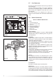
FIG. 2.30 A16 1 2 3 4 5 6 7 8 Wh Wh Rd Blk Rd Wh Rd Bl CN205 M A ON N CN206 L H B 1 2 3 4 5 6 CN303 O FUSE FUSE Q CN201 5 6 CN205 I CN300 CN203 CN201 CN200 Blk Blk Gry Gry Pnk Wh Rd CN206 Wh Wh Pnk Pnk CN203 Blk Blk Rd Gry Gry Gry Gry or Bl Blk Blk CN302 CN302 P CN304 Blk Brn Brn Brn Bl Bl CN303 Bl Blk 2.
A - Dip Switches B - Summer/Winter Switch - Central Heating Temperature Regulation C - Connector for Remote Control (Climate Manager) D - Domestic Hot Water Temperature Regulation E - Soft-light Regulation F - Maximum Central Heating Temperature Regulation G - ON/OFF Selector H - EEPROM I - Time Clock Connector L - Release Push Button M - Economy/Comfort Selector N - EASY Teleservice (optional) P.C.B. Section O - Display P.C.B.
2.18 WATER CIRCUIT DIAGRAM FIG. 2.28 24 23 1 2 22 3 21 4 5 6 7 20 8 19 9 18 17 10 A B 11 C 12 LEGEND: 1. 2. 3. 4. 5. 6. 7. 8. 9. 10. 11. 12. 13. 14. 15. 16. 17. 18. 19. 20. 21. 22. 23. 24. Fan Heat Exchanger Overheat Thermostat Central Heating Flow NTC Burner Detection Electrode Ignition Electrodes Diverter Valve Low Water Pressure Switch Drain Valve Domestic Hot Water Temperature NTC Secondary Heat Exchanger Gas Valve D.H.W. Flow Switch D.H.W.
3. COMMISSIONING 3.1 INITIAL PREPARATION MTS (GB) Limited support the initiative. In Sections 11 and 12 of this manual you will find the commissioning checklist (page 78) and the service interval record (Page 79), It commissioning checklist is completed is important the in the presence of your customer, they are shown how to use it, and it is signed by them. Please instruct your customer that they must have this manual with them whenever they contact a service engineer or us.
Copal MB-1, or BetzDeaborn Sentinel X100 is recommended. NOTE: FAILURE TO CARRY OUT THE FLUSHING PROCEDURE WILL RESULT IN THE WARRANTY BECOMING VOID. In hard water areas or where large quantities of water are in the system the treatment of the water to prevent premature scaling of the main heat exchanger is necessary.
3.2 INITIAL START-UP E C A I 4 2 2 1 6 6 5 C 5 4 3 1 3 FIG. 3.2 E C D I 1 6 2 2 5 6 4 5 3 4 1 3 FIG. 3.4 30 THE CHECKS TO BE RUN BEFORE INITIAL START-UP ARE AS FOLLOWS: 1. Make sure that: - the screw on the automatic air valve has been loosened when the system is full; - If the water pressure in the system is below 1.5 bar, bring it up to the appropriate level; - Ensure that the gas cock is closed (FIG. 3.
3.3 OPERATIONAL ADJUSTMENTS A To access the areas in which adjustments are made, it is necessary to open the control panel, as indicated in SECTION 2.12, then remove the rear inspection cover by unscrewing the two screws “A”. Access is thereby provided to the P.C.B. and to the following components: 1. The power supply cable connector; 2. The fuses; 3. The soft-light potentiometer must be set to ensure correct ignition; 4.
3.7 BOILER SAFETY SYSTEMS WARNING! The boiler is still powered. E The boiler is protected from malfunctioning by means of internal checks by the P.C.B., which brings the boiler to a stop if necessary. There are two types of shut-off: • SHUTDOWN (A) • SAFETY SHUTDOWN (E) C D I 2 2 1 6 6 5 5 3 4 1 3 4 A ” SHUTDOWN “A This type of appliance shutdown is called “non-volatile”, and is indicated on the display by a number preceded by the letter (A) , and by the symbol (G FIG. 2.
ANTI-FROST DEVICE: The boiler is fitted with a device which, in the event that the water temperature falls below 3˚C, the burner ignites at the minimum power until the boiler reaches a temperature of approximately 33˚C. This device only operates if the boiler is functioning perfectly and: - the system pressure is sufficient; - the boiler is powered electrically; - the gas is turned on.
3.11 INSTRUCTING THE END USER 1. Hand over the copy of the End User Instructions supplied with the appliance, together with these instructions, and explain how to use the timeclock and room thermostat if fitted. 2. Show the End User how to switch the appliance off quickly, and indicate the position of the electric supply isolator. 3. Inform the End User of the location of all drains, isolating valves and air vents. 4.
4. GAS ADJUSTMENTS TABLE A CATEGORY II2H3+ Lower Wobbe Index (15°C;1013mbar) Nominal Delivery Pressure Minimum Delivery Pressure microGENUS HE 24 MFFI Main Burner: n. 14 jets (ø) Consumption (15°C; 1013mbar) max - min Consumption (15°C; 1013mbar) max - min Gas Burner Pressure max - min microGENUS HE 28 MFFI Main Burner: n. 14 jets (ø) Consumption (15°C; 1013mbar) max - min Consumption (15°C; 1013mbar) max - min Gas Burner Pressure max - min microGENUS HE 32 MFFI Main Burner: n.
4.2 ADJUSTING THE GAS PRESSURES Setting the minimum and the maximum power of the boiler 1. Check that the supply pressure and dynamic working pressure to the gas valve is a minimum of 20 mbar for natural gas. 1 2. To do this, loosen the screw “A”. Fit the pipe of the pressure gauge to the inlet pressure connection of the gas valve “B” and check for the correct standing pressure, then operate the appliance and check for the correct working pressure.
Setting the maximum heating circuit power CN206 CN203 CN200 1. To set the maximum heating circuit power, turn the On/Off knob to the “ON” position and set the time clock and any external controls to the “ON” position. Turn the knob of the heating thermostat clockwise to maximum. CN201 A 2 Soft-light Adjustment 2. Remove the inspection panel of the P.C.B. and fit a small crosshead screwdriver in to the right hand potentiometer.
microGENUS HE 24 MFFI TABLE B NATURAL GAS (G20) kW 10.4 12 13 15 19 21 23,3 mbar 2.0 2.1 3.1 4.2 5.4 6.9 8.5 LPG (G30) kW 10.4 12 13 15 19 21 23,3 mbar 5.5 7.3 8.6 12.0 19.3 23.5 29.0 LPG (G31) kW 10.4 12 13 15 19 21 23,3 mbar 7.7 10.2 12.0 15.3 24.6 30.0 37.0 microGENUS HE 28 MFFI NATURAL GAS (G20) kW 11.4 15 16 19 23 25 27 mbar 1.8 3.1 3.6 4.7 6.9 8.2 9.5 LPG (G30) kW 11.4 15 16 19 23 25 27 mbar 5.4 9.4 10.7 13.7 20.0 23.6 27.
FIG. 4.
5. 40 MAINTENANCE It is recommended that the following inspections be carried out on the boiler at least once a year: 1 - Check the seals for the water connections; replace any faulty seals; 2 - Check the gas seals; replace any faulty gas seals; 3 - Visual check of the entire unit; 4 - Visual check of the combustion process or analysis of combustion by-products (see SECTION 3.
6. SERVICING INSTRUCTIONS To ensure efficient safe operation, it is recommended that the boiler is serviced annually by a competent person. Before starting any servicing work, ensure both the gas and electrical supplies to the boiler are isolated and the boiler is cool. Before and after servicing, a combustion analysis should be made via the flue sampling point (please refer to SECTION 3.4 for further details). 2.
6.2.2 Removing the sealed chamber front cover 6.2.3 Removing the side panels 1. Remove the screws “C” (FIG. 6.5); 2. Lift the sealed chamber front cover from the locating pins (FIG. 6.6). 1. Remove the four screws “D” for each side panel (FIG.6.7); 2. Pull the panel away from the boiler at the base, then lift the panel up and remove from the boiler. FIG. 6.7 D C C D FIG. 6.5 D D FIG. 6.
6.3 ACCESS TO THE COMBUSTION CHAMBER 6.3.1 Removing the combustion cover 1. Remove the screws “E” (FIG. 6.8); 2. Lift off the combustion cover. FIG. 6.8 FIG. 6.10 6.3.3 Removing the electrodes E E E E Before carrying out this procedure, unscrew and slide the burner forward (see previous section). 1. Remove rubber gasket “G” (FIG. 6.11); 2. To remove the detection electrode disconnect the cable at its connection point close to the P.C.B. (FIG. 6.12); 3. Remove screw “H” (FIG. 6.13); 4.
6.3.4 Removing the main heat exchanger FIG. 6.13 1. Drain the boiler of water; 2. Remove the side panels (see 6.2.3) 3. Remove the overheat thermostat sensor “H” (FIG. 6.15); 4. Remove the clips “I” (FIG. 6.15); 5. Release the connection nut “J” (FIG. 6.16); 6. Release the connection nut “K” (FIG. 6.17); 7. Pull down the pipe (FIG. 6.18); 4. Pull it straight out (FIG. 6.19). H I H I FIG. 6.15 J FIG. 6.
N FIG. 6.18 FIG. 6.21 O FIG. 6.19 FIG. 6.22 6.3.5 Removing the air pressure switch 1. Disconnect the electrical connections “L” and silicone pipes “M” from their connection points (FIG. 6.20); 2. Remove screws “N” on the top of the sealed chamber (FIG. 6.21); 3. Lift out the air pressure switch; 4. Unscrew the two screws “O” to remove the switch from the plate (FIG. 6.22 - 6.23); 5. Reassemble in reverse order. FIG. 6.23 M L FIG. 6.
6.3.6 Removing the fan 6.3.7 Removing the condensate sensor 1. Remove screw “P” and remove the fan collar clamp “Q” (FIG.6.24); 2. Disconnect electrical connections “Q” and silicone pipe “Q” (FIG.6.25); 3. Remove fan and gasket “R” (FIG.6.26). 4. Reassemble in reverse order, ensuring the gasket “R” is seated correctly. 1. Disconnect electrical connections “S” (FIG.6.27); 2. Remove screws “T” and remove the condensate sensor (FIG.6.28 - 6.29). S P FIG. 6.24 FIG. 6.27 Q T Q FIG. 6.25 FIG. 6.
6.3.8 Removing the latent heat exchanger 1. Remove the U-clips “U” (FIG.6.30); 2. Remove the clamp “V” to disconnect the condensate trap tube (FIG.6.31); 3. Loosen the nut “W” (FIG.6.32); 4. Remove the four screws “X” (FIG.6.33); 5. Remove the latent heat exchanger (FIG.6.34 - 6.35); 6. Reassembled in reverse order. X X U FIG. 6.33 FIG. 6.30 FIG. 6.34 V FIG. 6.31 FIG. 6.35 W FIG. 6.
6.3.9 Removing the Recuperator 6.3.10 Removing the Condensate Trap 1. 2. 3. 4. 1. 2. 3. 3. 4. Remove the latent heat exchanger - see paragh. 6.3.8 Unscrew the two screws “Y” (FIG.6.36); Remove the recuperaor (FIG.6.37); Reassemble in reverse order. THE Remove the clamp “Z” (FIG.6.38); Remove the clamp “A1” (FIG.6.39); Unscrew and remove the trap from the boiler (FIG.6.40); Remove the trap (FIG.6.41).
6.4 ACCESS TO THE GAS VALVE 6.4.2 Removing the gas valve (Honeywell) Important! Before removing the gas valve, ensure the gas supply is turned off. 6.4.1. Removing the spark generator 1. Disconnect the ignition leads “A2” by pulling upward (FIG. 6.42); 2. Remove the screw “A3” (FIG. 6.43); 3. Remove the spark generator by pulling forward from the gas valve (FIG. 6.44). 1. Disconnect all the cables from the solenoid and modureg; 2. Remove the spark generator (see previous section); 3.
6.5 ACCESS TO THE WATER CIRCUIT Important! Before any component is removed, the boiler must be drained of all water. 6.5.1 Removing the D.H.W. (secondary) exchanger 1.Remove the condensate trap - see parag. 6.3.10; 2.Remove the screws “A6” (FIG 6.48); 3.Disconnect the cable “A7” (FIG 6.49); 4.Push the insulation of the exchanger towards the rear of the boiler, and lift upwards and remove from the front of the boiler (FIG 6.50); 5.
6.5.2 Removing the pump pressure switch 6.5.3 Removing the safety valve 1. Remove the pump pressure switch electrical connections “A8” (FIG 6.52); 2. Unscrew the pump pressure switch by using a spanner on the nut (FIG 6.53); 3. Remove the pump pressure switch (FIG 6.54). 1. Disconnect the discharge pipe work from below the boiler; 2. Unscrew the fixing screw “A9” (FIG. 6.56) 3. Pull the valve upwards to remove (FIG. 6.57). A8 A8 FIG. 6.55 FIG. 6.52 A9 FIG. 6.53 FIG. 6.56 FIG. 6.54 FIG. 6.
6.5.4 Removing the automatic air vent 6.5.5 Removing the pump 1. Remove the U-clip “B1” (FIG. 6.58); 2. Remove valve complete with float using a screwdriver (FIG 6.59-FIG 6.60). 1. Remove the electrical connetction “ B2” (FIG. 6.61); 2. Release the nut “B3” (FIG. 6.62); 3. Remove the retainig clip “B4” from the buttom of the boiler (FIG. 6.63); 4. Remove the screws “B5” (FIG. 6.64); 5. Remove the U-clip “B6” and remove the pressure gauge connection (FIG. 6.65); 6.
6.5.6 Removing the pressure gauge 1. Remove the U-clip “B8” (FIG. 6.67) 2. Push the pressure gauge through the control panel from the rear using a screwdriver (FIG. 6.68-6.69). B5 FIG. 6.64 B8 B6 FIG. 6.67 FIG. 6.65 B7 FIG. 6.68 FIG. 6.66 FIG. 6.
6.5.7 Removing the expansion vessel 6.5.8 Removing the overheat thermostat 1. 2. 3. 4. 1. Disconnect the overheat ther mostat electrical connections “C2” (FIG. 6.73); 2. Then remove the thermostat from its mounting by releasing the securing clip (FIG. 6.74-6.75). If rear exit flue, remove the flue; Release nut “B9” (FIG. 6.70); Remove back-nut “C1” (FIG. 6.71); Remove the expansion vessel (FIG. 6.72). C2 B9 FIG. 6.70 FIG. 6.73 FIG. 6.71 FIG. 6.74 FIG. 6.72 FIG. 6.
6.5.9 Removing the C.H. temperature sensor (N.T.C.) 1. Pull off the electrical connector and remove the sensor probe using a suitable spanner (FIG. 6.76-6.77). 6.5.10 Removing the D.H.W. temperature sensor (N.T.C.) 1. Pull off the electrical connector and unscrew the sensor probe using a suitable spanner (FIG. 6.78). FIG. 6.76 FIG. 6.78 6.5.11 Removing the diverter valve actuator 1. Unplug the electrical connector “C3” (FIG. 6.79); 2.
6.5.12 Removing the D.H.W. flow switch 6.6 ACCESS TO THE CONTROL SYSTEM 1. Unplug the electrical connector “C5” (FIG. 6.80); 2. Remove the D.H.W. flow switch using a screwdriver (FIG. 6.81-6.82). Important! Isolate the electrical supply to the boiler before accessing the control panel. 6.6.1 Checking the fuses 1. Remove the inspection cover on the reverse of the control panel and unscrew the screws “C6”(FIG. 6.83); 2. Remove the fuses (FIG. 6.84). C5 FIG. 6.80 C6 C6 FIG. 6.83 FIG. 6.81 FIG. 6.
6.6.2 Removing the P.C.B. 1. Isolate electricity; 2. Remove the inspection cover from the reverse of the control panel, unscrew the screws “C7” (FIG. 6.85); 3. Unplug all electrical connections from the recuperator P.C.B on the reverse of inspection cover (FIG. 6.86); 4. Unscrew the recuperator P.C.B mounting screws “C8” (FIG. 6.87); 5. Unplug all electrical connections from the P.C.B.; 6. Unplug carefully the EEPROM “C9” (FIG. 6.88); 7. Remove the screws “D1” (FIG. 6.89); 8.
6.6.3 Removing the time clock 1. Disconnect the electrical connections “D5” from the clock (FIG. 6.93); 2. Remove screws “D6” (FIG. 6.93); 3. Lift out the time clock from the control panel (FIG. 6.94). D4 D4 D5 FIG. 6.91 D6 FIG. 6.93 FIG. 6.92 FIG. 6.94 PRELIMINARY CHECKS MAKE SURE THAT: 1 - There is sufficient water in the system 2 - The gas is turned on 3 - The electrical supply is turned on TURN ON THE ON/OFF SWITCH IS THE POWER DISPLAY ON? NO 1. Check the fuses 2.
7. FAULT FINDING 7.1 FAULT FINDING GUIDE (FLOW-CHARTS) These fault finding guides are not exhaustive. However, it is possible to detect and correct many defects by using the standard fault finding diagrams described in this chapter, ensure these guides are carried out in the set order.
A IS THE PUMP RUNNING? NO YES POWER TO THE PUMP? YES NO 1. Check pump cable 2. Check/replace main P.C.B. IS THE LOW WATER PRESSURE SWITCH WORKING CORRECTLY? E02: does not close NO 1. Check if there is air in the system 2. Check the main circuit flow switch operation 3. Check the pressure on the water gauge and fill system to 1 bar YES Release/replace pump YES Turn the ON/OFF button B B IS THE FAN RUNNING? NO DOES CODE E33 APPEAR? YES NO Replace the main P.C.B.
B IS THE FAN RUNNING? NO DOES CODE E33 APPEAR? YES NO Replace the main P.C.B. IGNITION SPARKS ARE GENERATED REGULARLY? NO YES 1. Check the fan cable 2. Replace the fan 3. Replace the main P.C.B. 1. Check/replace ignition electrode 2. Check ignition cable 3. Check/replace the main P.C.B. YES IS THE BURNER ALIGHT? YES 1. Check the power supply of the gas valve. 2. Check for an air pressure signal NO 3. Check the gas pressure on the burner 4. Check the soft-light adjustment 5.
8.
code 65100547 601 401 601 606 402 602 602 608 604 610 605 603 607 403 601 609 603 611 code 65101257 code 65102576 501 702 701 503 502 701 504 705 703 704 701 701 701 63
Key no. 18 19 22 25 26 27 30 32 42 46 54 72 72 73 80 80 81 82 84 87 89 90 93 106 108 110 111 112 118 126 127 64 G.C. part no.
General Info Name CE Certification Flue Type Energy Performance Heat Input max/min (Central Heating) Heat Output max/min Efficiency of Nominal Heat Input (60/80°C) Efficiency of Nominal Heat Input (30/50°C) Efficiency at 30% of Nominal Heat Input (30°C) Efficiency at Minum Input Efficiency (Dir.
General Info Name CE Certification Flue Type Energy Performance Heat Input max/min (Central Heating) Heat Output max/min Efficiency of Nominal Heat Input (60/80°C) Efficiency of Nominal Heat Input (30/50°C) Efficiency at 30% of Nominal Heat Input (30°C) Efficiency at Minum Input Efficiency (Dir. 92/42/EEC)** SEDBUK Rating Heat Loss to the Casing ( T=50°C) Flue Heat Loss with Burner Operating Flue Heat Loss with Burner Off Band % % % B 0,7 2,6 0.
11.
12.
Merloni TermoSanitari SpA - Italy Commercial subsidiaries: MTS (GB) LIMITED MTS Building Hughenden Avenue High Wycombe Bucks HP13 5FT Telephone: (01494) 755600 Fax: (01494) 459775 Internet: www.mtsgroup.com/uk E-mail: info@uk.mtsgroup.com Technical Advice: 0870 241 8180 MTS Heating Limited Damastown Industrial Park Damastown Avenue Mulhuddart Dublin 15 Telephone: (01) 810 3723 Fax: (01) 810 3727 Internet: www.mtsgroup.com/ie E-mail:info@ie.mtsgroup.
End User Manual microGENUS HE 24 MFFI microGENUS HE 28 MFFI microGENUS HE 32 MFFI C E I 3 4 2 5 4 2 6 1 6 5 Country of destination: GB 1 3
Dear Customer, Thank you for choosing an ARISTON boiler. We guarantee that your boiler is a reliable and technically sound product. This manual provides detailed instructions and recommendations for proper installation, use and maintenance. Remember to keep this manual in a safe place for future reference i.e. by the gas meter. Your local MTS Servicing Centre is at your complete disposal for all requirements. The guarantee on this appliance is valid for 24 months from the first day of installation.
1. GENERAL INFORMATION MTS (GB) Limited support the initiative. Your installer will give you, and show you how to use, a Log Book which will give you important information about your boiler, and heating system. Please have this Log Book to hand whenever you contact a service engineer or us. All CORGI Registered Installers carry a CORGI ID card, and have a registration number. Both should be recorded in your boiler Logbook.
CONTROL PANEL I E J K C I 2 2 6 6 5 1 4 5 4 1 3 3 LEGEND: * Warning! the flue analysis mode must only be selected by a qualified service engineer. 2.
PRACTICAL TIPS - If the water is very hard, it is recommended that a water softener be added to the system so as to reduce the formation of limescale in the boiler exchangers. This will ensure that the efficiency of the unit remains the same over time, reducing gas consumption and maintenance costs. - If the boiler should be out of use for a prolonged period, it is recommended that the electrical power supply be disconnected and that the external gas cock be closed.
ECONOMY/COMFORT E E C E confort economy C PL006D C The selector knob “E” allows the user to choose the economy mode (position “E”) or the comfort mode (position “C”). The economy mode is the normal state for the operation of the boiler, since the domestic water is heated up only when a tap is turned on.
Other Shutdown Situations Should a shutdown situation indicated on the display by the following letters and figures occur, E04, E05, E06, E07, E08, E09, E20, E21, E33, E34 contact one of our Authorised Service Centres. If instead the display shows one of the shutdown situations indicated by the following letters and figures, A77, A78, A97, A98, A99, try resetting the boiler by pressing the reset button “D”. If the boiler shuts off again, contact one of our Authorised Service Centres.
ANOTE: the time clock is for central heating control only. The time clock is provided with 96 switches, called riders, each of which covers a time interval of 15 minutes (four per hour). When a rider is switched from the inside (off setting) to the outside of the clock border (on setting), the circuit is closed (switch on) for a period of 15 minutes and then the boiler starts if the room thermostat (if installed) or the heating thermostat require heat (heating function on). 6.
SPARE PARTS EXPLODED VIEW GAS WALL BOILERS Models MICROGENUS 24 MFFI HE MICROGENUS 28 MFFI HE MICROGENUS 32 MFFI HE ER2004210047001001 Edition 1 of 10 November 2004
67 66 65 64 63 62 61 60 59 58 57 56 55 1 305 53 305 304 54 58 53 10 2 10 129 128 3 53 68 4 10 53 10 69 70 5 6 301 127 124 125 71 123 7 8 9 10 10 75 11 12 122 73 31 74 76 19 121 52 20 51 77 77 120 119 50 118 14 15 79 14 15 80 84 85 95 93 94 97 96 88 112 45 106 44 105 100 44 43 42 41 104 103 22 98 58 46 107 89 87 21 111 110 91 90 86 108 92 89 47 116 109 113 84 19 20 115 82 83 17 48 117 31 114 81 16 18 49 44 78 13 303 1
CODE -----998616 998776 998581 990662 990665 65102548 571562 -----570717 990695 65102070 65100684 998077 998064 65100706 998483 997147 998424 61010609 65100682 573520 65100547 573727 569390 995903 998458 65101257 65100704 65100249 65102587 65101417 65100680 65101353 65100699 65100687 65100690 -----65100686 -----65100678 65100676 999599 569711 65100677 65100695 998517 ----------65100705 65100698 65102559 65100879 65102164 990373 65101317 573329 65102166 65102584 65102560 -----998565 998636 995315 999980 6510
ER2004210047001001 PART.
PART. CODE DESCRIPTION 129 65102574 Plug 301 302 303 304 305 65101352 998596 65101351 998607 995305 801 802 998716 998717 REF. NOTE Case panel (L.H. side) Insert case Case panel (R.H.
code 65100547 601 401 601 606 402 602 602 608 604 610 605 603 607 403 601 609 603 611 code 65101257 code 65102576 501 702 701 503 502 701 504 705 703 704 701 701 701 CODE 998974 998975 998718 DESCRIPTION Heating actuator bush 3-Way spring kit (D.H.W.) 3-Way spring kit (C.H.) REF. 501 502 503 504 65100540 65100541 65100869 65100776 Flow detection kit with magnet 3-Way spring kit (D.H.W.