
Technical information


6
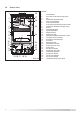
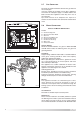
After remo
ving the boiler from its pac
kaging, remo
ve the
template from the separ
ate bo
x containing the connection
kit. N
OTE: Pay particular attention to any test water that
ma
y spill from the appliance.
Place the template in the position the appliance is to be
mounted and after ensuring it is hanging squarely, use it
to mark the holes for the hanging bracket, connection kit
and flue pipe(s)
NB: For further information relating to the
flue installation please refer to Section 2.9 F
LUE
CONNECTION. (If the appliance is to be fitted on a wall of
combustible material, the wall must be protected by a
sheet of fireproof material).
If the appliance is to be fitted into a timber framed
building, guidance should be sought from the Institute of
2.5 MOUNTING THE APPLIANCE
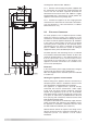
FIG. 2.2
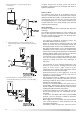
In order to allow access to the interior of the boiler for
maintenance purposes, the boiler must be installed in
compliance with the minimum clearances indicated in
FIG. 2.2
2.4 CLEARANCES
120
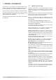
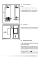
LE
GEND
:
A = Central Heating Flow (3/4” - 22mm Copper Tail)
B = Domestic Hot Water Outlet (1/2” - 15mm Copper Tail)
C
= Gas Inlet (3/4” - 15mm Copper Tail)
D = Domestic Cold Water Inlet (1/2” - 15mm Copper Tail)
E = Central Heating Return (3/4” - 22mm Copper Tail)
2.3 OVERALL DIMENSIONS
FIG. 2.1