
Technical information


7
For safety purposes, have a competent person carefully
check the electrical system in the property, as the
manufacturer will not be held liable for damage caused by
the failure to earth the appliance properly or by anomalies
in the supply of power. Make sure that the residential
electrical system is adequate for the maximum power
absorbed by the unit, which is indicated on the rating
plate. In addition, check that the section of cabling is
appropriate for the power absorbed by the boiler.
The boiler operates with alternating current, as indicated
in the Technical Information table in Section 10, where the
maximum absorbed power is also indicated. Make sure
that the connections for the neutral and live wires
correspond to the indications in the diagram. The
appliance electrical connections are situated on the
reverse of the control panel.
IMPORTANT!
In the event that the power supply cord must be changed,
replace it with one with the same specifications
.
Note: The diagrams for the electrical system are indicated
in section 2.13.
W
arning, this appliance must be earthed.
Exter
nal wir
ing to the appliance m
ust be carr
ied out by a
competent person and be in accordance with the current
I.E.E. Regulations and applicable local regulations.
The appliance is supplied with a fly-lead already
connected, this m
ust be connected to a 240v supply
fused at 3A and must facilitate complete electrical
isolation of the appliance, by the use of a fused double
pole isolator ha
ving a contact separ
ation of at least 3 mm
in all poles or alternatively, by
means of a 3 A fused
three pin plug and unswitched, shuttered socket outlet
both complying with BS 1363.
The point of connection to the Electr
icity supply m
ust be
readily accessible and adjacent to the appliance unless
the appliance is installed in a bathroom when this must
be sited outside the bathroom (see section 2.2).
Should external controls be required, the design of the
external electrical circuits should be undertaken by a
competent person, see Section 2.13 for further
information.
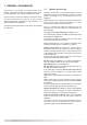
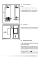
2.6 EL
ECTRICAL
CO
NNECTION
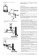
FIG. 2.3
Gas Engineers document RE
F
: IGE/UP/7.
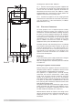
2.5.1. Drill the wall and plug using those supplied with
the connections kit, position the hanging bracket and
secure with the wall bolts supplied, assemble the
connection kit and secure to the wall. NOTE: It is highly
r
ecommended that a spirit level be used to position the
appliance to ensure that it is perfectly level.
2
.5.2. Position the appliance on the hanging bracket
and connect the connection kit to the boiler connections.
(
see also Sections 2.7 Gas Connections, 2.8 Water
Connections & FIG. 2.3).