
Technical information


9
SA
FETY
VA
LVE
DI
SCHARGE
:
T
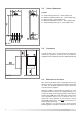
he discharge should terminate facing downward on the
exterior of the building in a position where discharging
(
possibly boiling water & steam) will not create danger or
nuisance, but in an easily visible position, and not cause
damage to electrical components and wiring.
The discharge must not be over an entrance or a window
o
r any other type of public access.
CONDENSATE DISCHARGE:
A flexible hose connected to the bottom of the boiler
should be inserted into a tundish (not supplied).
NOTE:IT MAY BE NECESSARY TO REMOVE THE CASING TO PULL
THE CONDENSATE HOSE OUT OF THE BOTTOM OF THE BOILER
.
The condensate discharge hose from the boiler must
have a continuous fall of at least 2.5° and must be
connected to a visible tundish and inserted by at least
50mm into a suitable acid resistant pipe with a nominal
diameter of 32mm e.g. plastic waste pipe or overflow
pipe. The condensate discharge pipe must have a
continuous fall and preferably be installed and terminated
within the building to prevent freezing.
The discharge pipe must be terminated in one of the
following positions, allowing for a safe discharge:
i) Connecting in to an internal soil stack (at least 450 mm
above the invert of the stack). A trap giving a water
seal of at least 75 mm must be incorporated into the
pipe run, there also must be an air break upstream of
the trap i.e. tundish.
ii) Connecting into the waste system of the building such
as a washing machine or sink trap. The connection
must be upstream of the washing machine/sink (If the
connection is down stream of the waste trap then an
additional trap giving a minimum water seal of 75 mm
and an air break must be incorporated in the pipe run,
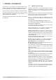
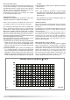
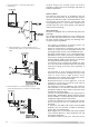
VR003A
RESIDUAL HEAD OF THE BOILER
∆∆
T 20°C
as above.
i
ii)Terminating into a gully, below the grid level but above
the water level.
i
v)Into a soakway.
N
O
TE
: If any condensate pipe work is to be installed
externally, then it should be kept to a minimum and be
i
nsulated with a waterproof insulation and have a
c
ontinuous fall.
Some examples of the type of condensate drains can
be found on pages 10 and 11.
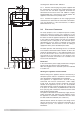
AIR RELEASE POINTS:
These must be fitted at all high points where air naturally
collects and must be sited to facilitate complete filling of
the system.
The appliance has an integral sealed expansion vessel to
accommodate the increase of water volume when the
system is heated.
It can accept up to 6 litres (1.3 gal) of expansion water. If
the heating circuit has an unusually high water content,
calculate the total expansion and add an additional
sealed expansion vessel with adequate capacity. This
should be located on the return pipe work as close as
possible to the pump inlet.
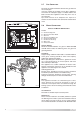
MAINS WATER FEED - CENTRAL HEATING:
A method for initially filling the heating system is supplied
with the connection kit. The filling loop is connected
between the cold water inlet and the central heating flow
connections, and incorporates a non-return valve. To
operate the filling loop, it is necessary to open both
quarter turn handles, once the required pressure has
been achieved, close both handles and disconnect the
hose in accordance with water byelaws. N
OTE: The
installer should ensure that there are no leaks as
FIG. 2.6