
Installation Guide

S
AMPLE PANEL LAY
OUT
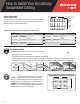
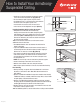
Determine panel layou
t
For best appearance, border panels should be the same size on the opposite
sides of the room and as large as possible. Use your room dimensions and
follow the formula in the worksheets below
.
Sample worksheets using 2' x 4' panels in a 9' x 10' 6" roo
m
IN
S
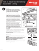
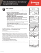
TALL WALL M
O
LDIN
G
• Mark the desired height of your new ceiling on the wall
(
A
).
• Add the height of the Wall Molding above the desired ceiling height and mark a level line around 3 walls
(B).
•
U
se a str
i
ng
li
ne to mar
k
t
h
e 4t
h
wa
ll.
• Fasten wall molding to the wall studs with appropriate
f
astener. (
C
)
.
• If nailin
g
moldin
g
directly to wall is not possible
(
for example, a solid concrete or stone wall
)
,
han
g
a section of main
b
eam next to the wall as a substitute for re
g
ular wall moldin
g
usin
g
han
g
er wire
(D)
or the QuickHan
g
hardware
(E).
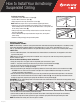
INSTALL HANGER WIRE OR QUICKHANG GRID HOOKS
IMPORTANT:
The
fi
rst row o
f
main beams in a 2' x 4' panel
installation should be the border panel size from the wall.
In a 2' x 2' panel installation, the
fi
rst main beam can be the
border panel size or the border panel + 24" from the wall.
EXAMPLE
:
See Sample Room Han
g
er Layout – 2' 6" from the
wall for a 2' x 4' panel. QuickHang brackets should not be
spaced more than 4' apart in any direction
.
How to Install Your Armstrong
®
Suspended Ceiling
LA2
9
4
998
-41
8
2'6"
2'6"
1' 3" 1' 3"
10' 6"
9'
Wi
d
th
o
f
border
p
ane
l
M
a
i
n
b
eams
4
'
apar
t
Length o
f
bo
r
de
r
pane
l
C
ross tees 2' apar
t
Determine length of border panels
9
'
4
'
R
oom lengt
h
Panel
length
(
2) 4' panels + 1
f
oot remainde
r
Til
es across roo
m
1
'
4
'
Re
ma
in
der
P
an
e
l length
5
'
Tile borders (both sides)
5
'
2
Number of panels
2
'
6
"
B
or
d
er pane
l
l
engt
h
÷
+
÷
Determine width of border panels
10' 6"
2'
Room widt
h
Panel widt
h
(5) 2' panels + 6 inches remainde
r
T
iles across roo
m
6
"
2
'
R
ema
i
n
d
e
r
Pan
e
l
widt
h
2' 6
"
T
ile borders (both sides
)
2
'
6
"
2
Number of panels
1
'3"
B
or
d
er
p
ane
l
w
id
t
h
÷
+
÷
STEP
1
2'6"
•••
••
•
4'4'
4' 4'
2'6"
4'
Joists
10'6"
9'
Hanger location
S
ample Han
g
er Layout
f
or 2'x 4'
C
eilin
gs
STEP
2
Mark desired
ceiling height
from floor
Joist
Level line
B
A
C
Ou
t
s
i
de
corner
C
In
s
i
de
corner
Use Main Beam
instead of Wall
Molding
D
D
Main beam
Place
grid hooks in
round holes
E
U
s
i
ng
H
anger
Wi
re Using
Q
uickHang
G
rid Hook
s