
Humidifier User Manual

5
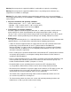
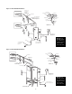
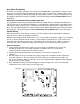
See Detail “A”
Pitch Min. 1” Per
12” Back to Unit
2” Insulated Copper
“P” Trap Drain Every
20’ of Piping or at
Bottom of Vertical Run
Pitch Min. 1” Per
12” Back to Unit
1” ID Hose
Air Gap
1” Copper (Min) Pitched
1” per 12” (Min) to
Open Drain
Water in 3/8” Copper
Type with Ball Valve
24”
Clearance
Fused Disconnector
Magnetic Breaker
within Sight of Unit
Hose Clamp
Steam Hose or Copper
Hose
Soldered Joints
1/2” or 3/8”
Copper Tube
UP
Full Size Tee
2” Copper Tee
Reducer
6” Min.
To Drain
Detail “A”
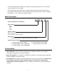
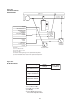
24”
See Detail “A”
Pitch Min. 1” Per
12” Back to Unit
“P” Trap Drain
Every 20’ of Piping
or at Bottom of Vertical Run
24”
2” Insulated Copper
24”
1” Copper (Min) Pitched
1” Per 12” (Min) to Open Drain
1” ID Hose
Air Gap
Fused Disconnector
Magnetic Breaker
within Sight of Unit
Water in 3/8” Copper
Type with Ball Valve
Hose Clamp
Steam Hose or Copper
Hose
Soldered Joints
1/2” or 3/8”
Copper Tube
Full Size Tee
2” Copper Tee
Reducer
To Drain
UP
Detail “A”
Figure 5-1 HC-6100/6300 Installation
Figure 5-2 HC-6500/6700 Installation
Note: On all
HC6000 models
24” clearance is
required on both
sides and the
front of the unit.
Note: On all
HC6000 models
24” clearance is
required on both
sides and the
front of the unit.