
Humidifier User Manual

Area Steam Distribution
The EHF-3 fan package (minimum of 2 required for HC-6500/6700) is designed to be hung on a wall
to operate as a remote mounted, direct area discharge option. It incorporates a blower rated at 120v-
2.90 amps. CFM rating is 465 @ 1530 RPM. The fan package requires a separate 120 volt power sup-
ply (optional step down transformer available). Consult Armstrong Installation Bulletin IB-95 for more
information.
Alternative for shortened non-wettable vapor trail
For applications with particularly limited downstream absorption distance, Armstrong HumidiPack or
ExpressPack may be considered. HumidiPack is a prefabricated separator/header and multiple disper-
sion tube assembly. ExpressPack is a multi-tube steam dispersion panel which is shipped unassem-
bled. The Armstrong HumidiPack or ExpressPack provide uniform distribution and shortened non-wet-
ting vapor trail. Consult Armstrong Installation Bulletin No. 560 or Bulletin 573 for more information.
Control Wiring
When knock-out for sensor wiring is removed, an IP65 compliant cable bushing will be required to
keep the electric cabinet in compliance with IP32.
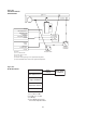
Wiring for low voltage controls should not be run in same conduit as the power supply. Use of shielded
wire or a separate dedicated metal conduit is required. When shielded cable is used, shield is to be
grounded at the humidifier only. The wire should not be longer than 30 meters (100 ft). If the wire is
out of this limit, please contact Armstrong. Refer to Figures 10-1 and 10-2 for wiring schematics.
Control Humidistat
1. Locate control humidistat where it will sense the average air condition of the space to be
humidified. Avoid areas of restricted circulation or locations where the sensor will be
subjected to drafts, localized heat or moisture sources.
2. Optional duct mounted humidistats are available to sense return or exhaust air, if
preferred.
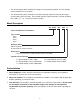
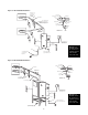
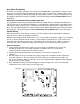
3. Set DIP switch S-2 on the PC board to the proper range for the humidistat control signal to be
used. See Figure 9-1 . Also set voltage source DIP switch (S1 and S3) to proper range. See
Fig. 9-1 for location of switches and pages 10 and 11 in tandem with the applicable wiring diagram
below for correct switch settings.
4. Wire standard Armstrong 0-10 Vdc humidistat as shown in Figure 10-1. For use of alternative
humidistats or RH sensor, please refer to Figure 10-2.
9
Figure 9-1