DTR Sensor Transmitter INSTRUCTIONS Installation and Operation of the AMC-DTR Sensor Transmitter IMPORTANT: Please read these installation and operating instructions completely and carefully before starting. Filename: Manual_amc-DTR ver 2.5.doc Copyright ©, July 18, 2011, AMC The Armstrong Monitoring Corporation 215 Colonnade Road South, Ottawa, Ontario, Canada K2E 7K3 Tel: (613) 225-9531 • Fax: (613) 225-6965 • U.S. Toll Free: (800) 465-5777 E-mail: gas@armstrongmonitoring.com • Internet:www.
AMC-DTR Sensor Transmitter User Manual
AMC-DTR Sensor Transmitter User Manual TABLE OF CONTENTS Section Title Page 1 GENERAL INFORMATION ..................................................................................... iii 1.1 WARRANTY.......................................................................................................iii 1.2 LIABILITY...........................................................................................................iii 1.3 PRODUCT RETURN ..........................................................
AMC-DTR Sensor Transmitter User Manual 7.2 7.3 7.4 Configuration Using the Magnetic Wand.......................................................... 22 System Configuration Menus ........................................................................... 22 Alarm Settings.................................................................................................. 23 7.4.1 7.5 7.6 7.7 7.8 7.9 7.10 Sensor Information......................................................................................
AMC-DTR Sensor Transmitter User Manual 1 GENERAL INFORMATION 1.1 WARRANTY The AMC-DTR is warranted against defects in material and workmanship for a period of two years from date of delivery. Maintenance items are not warranted. During the warranty period, The Armstrong Monitoring Corporation will repair or replace components that prove to be defective in the opinion of AMC.
AMC-DTR Sensor Transmitter User Manual 1.4 CONTACT INFORMATION For information please call 1-800-465-5777 or through contacts at www.armstrongmonitoring.com or through email directly at support@armstrongmonitoring.com. 1.5 MODIFICATIONS AND SUBSTITUTIONS Due to an ongoing development program, AMC reserves the right to substitute components and change specifications at any time without incurring any obligations.
AMC-DTR Sensor Transmitter User Manual 2 PRODUCT INFORMATION 2.1 Transmitter Sensor/transmitter Unit Order Number ………………………. Transmitter Part Number ……………………………………….. Transmitter Serial Number ……………………………………… Power Supply Requirement ……………………………………. 10 to 30 VDC Sensor Part Number ……………………………………………. Sensor Serial Number ………………………………………….. Optional Sensor Part Number …………………………………... Optional Sensor Serial Number ………………………………… 2.2 Factory Settings Sensor 1 Gas Type …………………………………… Range ………….
AMC-DTR Sensor Transmitter User Manual 3 SAFETY INFORMATION 3.1 Safety Information – Read Before Installation & Applying Power IMPORTANT Users should have a detailed understanding of AMC-DTR installation and operating instructions. Use the AMC-DTR only as specified in this manual or detection of gases and the resulting protection provided may be impaired. Read the following WARNINGS prior to use. WARNINGS • • • • • • • • • Recalibration is necessary when replacing the sensor.
AMC-DTR Sensor Transmitter User Manual 4 INSTALLATION INSTRUCTIONS 4.1 Introduction Important: This manual describes both the 2-Wire and the 3-Wire 4-20mA versions of the AMC-DTR. 2-Wire versions are only possible if using an electrochemical sensor and the DTR10-0232 Display PCB IS THE ONLY PCB IN THE ENCLOSURE. If the DTR-10-0233 I/O Power Supply is installed it is a 3-Wire version.
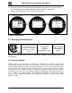
AMC-DTR Sensor Transmitter User Manual • • New smart sensors are recognized by the AMC-DTR and prompts users to either upload new configuration data or continue with data from the previous smart sensor. Sensors are industry proven for fast response and long life. Figure 1: Data Displays 4.2 Ratings and Certifications CSA certified for Division 1 & 2 hazardous area installations for explosion proof Class 1 Groups B,C,D Class 1 Groups A,B,C,D.
AMC-DTR Sensor Transmitter User Manual 4.4 Mounting the Enclosure The AMC-DTR standard enclosure is a cast aluminum explosion-proof (NEMA 7) enclosure as shown in Figure 2. Figure 3 shows dimensions with the dual local sensor ‘Y’ included. 4.96 5.00 3/4 NPT Hub 2 Places 4.94 0.276 Dia. 2 Places SENSOR HOUSING ALL DIMENSIONS IN INCHES Figure 2: AMC-DTR Explosion-Proof Housing 4.96 5.00 4.
AMC-DTR Sensor Transmitter User Manual Modular design simplifies the installation of the AMC-DTR. A top Display Assembly is mounted with captive thumbscrews and is easily removed to access field-wiring terminals. An optional DTR-10-0234 Alarms/Modbus board mounts piggyback to the back of the Display Assembly. Wiring from toxic or oxygen sensors terminates at the DTR-10-0232 Display Assembly along with 2-wire 4-20mA signal wires.
AMC-DTR Sensor Transmitter User Manual 4.5 System Design Specifications Supply Voltage: 10 to 30 volts Power Consumption: • Catalytic Combustible Sensors (requires DTR-10-0233 I/O Power Supply and 3-wire operation): 100 mA @ nominal 24 VDC • • Toxic/Oxygen Sensors without Relays / Modbus Option (2-wire 4-20mA operation): 25 mA @ nominal 24 VDC.
AMC-DTR Sensor Transmitter User Manual 4.6.1 2-Wire 4-20mA Mode Installation Description: The 2-wire current sinking transmitter is the easiest and most economical to install since there are only two wires. All of the power needed comes from the current loop and wire sizes may be smaller. However, only very low power applications are eligible for such transmitters. The AMC-DTR Display assembly shown in Figure 5 consumes <2.5 mA of quiescent current.
AMC-DTR Sensor Transmitter User Manual 4.6.2 3-Wire 4-20mA Mode Installation Description: 3-wire sourcing transmitters require an additional dedicated 24 VDC wire. The 4-20mA loop current is then delivered, or sourced, from the transmitter output and the receiver device must not provide 24 VDC from its input terminal.
AMC-DTR Sensor Transmitter User Manual 4.7 Alarms / RS-485 Modbus DTR-10-0234 Option Installation Description: The optional DTR-10-0234 Alarms/RS-485 Modbus board supplies two level alarm relays, a FAULT relay and an RS-485 ModBus RTU slave port (Figure 7). This board is “piggybacked” behind the DTR-10-0232 Display Assembly (Figure 5). Addition of this option requires 3-wire mode 4-20mA operation and thereby requires the DTR-10-0233 I/O Power Supply board (Figure 6).
AMC-DTR Sensor Transmitter User Manual a “star” pattern for reliable operation. The “end of line” unit should have J1 installed in the ‘A’ position for terminating resistor installation. All others should have J1 in the ‘B’ position. Front panel Rx / Tx LEDs are helpful troubleshooting tools. Figure 8: RS-485 Modbus Wiring 4.
AMC-DTR Sensor Transmitter User Manual 4.9 Sensor Installation (with Smart/Simple Sensor Definition) 3-wire electrochemical and catalytic bead sensors for toxic / oxygen and LEL combustible gas detection are offer as an industry standard. These are referred to as Simple sensors.
AMC-DTR Sensor Transmitter User Manual 4.9.1 Electrochemical Sensor Wiring to the DTR-10-0232 Display Connect the simple electrochemical sensor to TB2 on the DTR-10-0232 Display board. Note the colour of the wires for proper installation. Or connect the smart electrochemical sensor to S1 the DTR-10-0232 Display board as shown in Figure 11.
AMC-DTR Sensor Transmitter User Manual 4.9.2 Catalytic Bead Sensor Wiring to the DTR-10-0233 I/O Power Supply Connect the simple catalytic bead sensor to TB1 on the DTR-10-0233 I/O Power Supply board. Note the colour of the wires for proper installation. Or connect the smart catalytic bead sensor to S1 the DTR-10-0233 I/O Power Supply board as shown in Figure 12.
AMC-DTR Sensor Transmitter User Manual 4.9.3 Remote 2 and 3 wire 4-20mA transmitter wiring to the DTR-10-0233 I/O Power Supply Board(3 wire Shown) For DTR-10-0233 power supply boards that have been modified to accept a 4-20mA input, use the following wiring diagram for connection information. For AMC 2 wire transmitters connect Transmitters connect (-) to (in+) and transmitter (+) to (PWR) on DTR-10-0233 Power Supply.
AMC-DTR Sensor Transmitter User Manual 4.10 “Sensor Type” and AMC-DTR Signal Conditioning Catalytic bead and electrochemical sensors obviously have different signal conditioning requirements. In addition, same sensor types have different response coefficients, signal strength and gain and offset requirements. The block / wiring diagram in Figure 14 illustrates how AMC-DTR’s are able to accept many sensor types without the need of manual potentiometers or jumpers.
AMC-DTR Sensor Transmitter User Manual 5 INITIAL START-UP 5.1 “Transmitter Configuration” Menu Figure 15 shows the AMC-DTR XMITTER CONFIG menu used to activate channels, precisely calibrate 4-20mA outputs and set time / date. Its menus are set at the factory and typically not needed by the user. To access from any data display, press and hold the NEXT key for 5seconds until the screen appears requesting a special key sequence (4-UP keystrokes). Figure 15: Transmitter Configuration Menu 5.1.
AMC-DTR Sensor Transmitter User Manual higher value in order to achieve the correct voltage at the sensor. Correct sensor voltage should be confirmed after start-up for locally and remotely mounted catalytic bead sensors. 5.2.2 Initial Catalytic Bead LEL Monitor “Balance” Check Catalytic bead sensors connect to a bridge circuit that may require a balance adjustment after installation especially when the sensor is remote mounted from the AMC-DTR.
AMC-DTR Sensor Transmitter User Manual 6 OPERATING INSTRUCTIONS 6.1 Routine Sensor Calibrations Calibration is the most important function for insuring correct operation of the AMC-DTR. The CAL MODE (flow chart shown in Figure 17) is designed to make calibration quick, easy and error free. A successful ZERO and SPAN calibration requires only four keystrokes. The 420mA output transmits 3mA during CAL MODE and 4mA during the subsequent CAL PURGE delay to prevent external alarms during calibration.
AMC-DTR Sensor Transmitter User Manual Use the following step-by-step procedure to perform ZERO and SPAN calibrations. 1. To enter the CAL MODE from either data displays, press the DOWN / CAL key and within 5 seconds press the EDIT key. 2. Using the appropriate calibration adapter, apply a clean ZERO gas or be sure there is no background target gas in the monitored area. After the reading is stable, (approximately 1 minute) press the EDIT key to perform a ZERO calibration. 3.
AMC-DTR Sensor Transmitter User Manual 6.2 Alarm Operation AMC-DTR’s have front panel LED indicators for Alarm 1, Alarm 2 and Alarm 3. An optional DTR-10-0234 Relay/Modbus board adds K1, K2 & K3 relays for these alarms. CAUTION: AMC-DTR Alarm LED indicators function even without the presence of the DTR-10-0234 Relay option. With 2-Wire 4-20mA operation, to conserve power, alarm LED’s only flash during alarm events.
AMC-DTR Sensor Transmitter User Manual 7 SETUP MENU CONFIGURATION 7.1 Menus Database Configuration All AMC-DTR configuration variables are stored in its menu database. Many menu items will contain default values from the factory and require changes to better match a user’s particular application. AMC-DTR menus may be configured from the magnetic keypad in 5-10 minutes per transmitter.
AMC-DTR Sensor Transmitter User Manual 7.2 Configuration Using the Magnetic Wand Passing the magnetic wand past the EDIT key, from either data display, displays SETUP PAGE 1 as shown in Figure 19. The UP / DOWN keys maneuver the pointer while EDIT enters sublevels of menu items. All SETUP menu items have at least one page of sub-menus. Items with sub-menus are indicated by the > symbol (right hand pointing arrow) at the end of each line.
AMC-DTR Sensor Transmitter User Manual Readout Deadband allows forcing low values to continue to read zero. This is useful when there are small amounts of background gases that cause fluctuating readouts above zero. The highest amount of deadband allowed is 5%. The 4-20mA output is not affected by this menu item. Track Negative, set to NO, causes negative values to read the Zero (0%) value in data displays.
AMC-DTR Sensor Transmitter User Manual Alarm 1, 2, 3 menus are identical A L A RM Al a Al a Al a Re l Al a r r r a r m m m ys m S E T T I N GS 1 2 3/ Fai l Co n f i g .
AMC-DTR Sensor Transmitter User Manual K1 / K2 Failsafe set for YES means the relay de-energizes during alarm and energizes with no alarm. This is useful for also signaling alarm when AMC-DTR power is lost. K3 is a FAULT alarm and is always failsafe. K2 Acknowledge set for YES means the UP / RESET key (RESET key during either data display) will set K2 to the normal state EVEN when an Alarm 2 condition exists. This is useful for silencing an audible device, driven from K2, during the alarm condition.
AMC-DTR Sensor Transmitter User Manual Recent Cal displays the most recent calibration date. 7.6 CLOCK/DELAY Setup Since the AMC-DTR is equipped with a Real Time Clock & Calendar Time and Date must be set to correctly match its location. They are set at the factory in a 24 hour format but may require adjustment to match the location’s time & date after shipment. Follow the procedure in Configuration Using the Magnetic Wand in section 7.2.
AMC-DTR Sensor Transmitter User Manual There are two Diagnostics menus useful for driving outputs without exposing the sensor to the target gas. The OUTPUT SIMULATION menu allows setting the 4-20mA output to virtually any desired value. This is useful for checking responses of devices receiving the AMC-DTR’s 420mA output. The ACTIVATE RELAYS menu allows tripping of alarm relays (if equipped) without tripping alarm set-points with the target gas.
AMC-DTR Sensor Transmitter User Manual K1 K2 K3 2007 2008 2009 2 2 2 NA NA NA Read/Write Coils: Alarm Ack/Reset 12001 1 5 Note: After writing a TRUE to this register, it resets back to FALSE automatically. Read Only Registers: A2D Raw Chan 1 31001 4 NA A2D Raw Chan 2 31002 4 NA 10 bit value representing the A2D value of 0 to 1023 after calibration constants are applied.
AMC-DTR Sensor Transmitter User Manual Memory Floating Point: Note: Returned as 15bit plus sign 2s complement with +/- 5% over/underrange applied. Consider over/underrange when scaling values to be displayed at the workstation. The following equation may be used to determine a value for display. Display Value = MODBUS Value [ (Span Value -Zero Value) 1.1] + {Zero Value - [(Span Value - Zero Value) .
AMC-DTR Sensor Transmitter User Manual Chan 1 Manual Offset Real Chan 1 Manual Offset Devisor 41019 41020 4 4 NA NA Chan 2 Cal Zero Real Chan 2 Cal Zero Devisor Chan 2 Cal Span Real Chan 2 Cal Span Devisor Chan 2 Zero Real Chan 2 Zero Devisor Chan 2 Span Real Chan 2 Span Devisor Chan 2 Fault Real Chan 2 Fault Devisor Chan 2 Alarm 1 Real Chan 2 Alarm 1 Devisor Chan 2 Alarm 2 Real Chan 2 Alarm 2 Devisor Chan 2 Alarm 3 Real Chan 2 Alarm 3 Devisor Chan 2 Manual Gain Real Chan 2 Manual Gain Devisor Chan 2 Ma