Model 35 PARTS MANUAL Version 30304 Ashland Industries Inc. 1115 Rail Drive P.O. Box 717 Ashland, WI. 54806 Ph: 877-634-4622 Toll Free Ph: 715-682-4622 Fx: 715-682-9717 www.ashlandind.
Model 35 Scraper HOW TO ORDER PARTS: IMPORTANT Parts must be ordered through your local authorized ASHLAND dealer. Be sure to state MODEL and SERIAL NUMBER of your machine, PART NUMBER, DESCRIPTION and QUANTITY needed. Unless this is done, we cannot provide prompt service or assure shipment of the correct parts. Ashland Industries weldable replacement parts are availabe to rebuild, modify or update your scraper to current factory specifications. INDEX Page 3.
OPERATORS AND MAINTENANCE INSTRUCTIONS This scraper is a durable piece of equipment and with proper care will yield many years of trouble free operation. The scraper requires a power source with TWO 4 way (double acting) hydraulic control valves. The scraper should be greased at all points where grease fittings are provided.
SAFETY SIGNAL WORDS Note the use of the signal words DANGER, WARNING and CAUTION with the safety messages. The appropriate signal word for each has been selected using the following guidelines: DANGER: Indicates an imminently hazardous situation that, if not avoided, will result in death or serious injury. This signal word is to be limited to the most extreme situations typically for machine components which, for functional purposes, cannot be guarded.
ASSEMBLY INSTRUCTIONS FOR MODEL 35 SCRAPER 1. A suitable hoist or lift should be available for assembly. 2. Pack wheel bearings with grease and install hubs to axle spindles. 3. Raise actuating frame over bucket and lower into place so that the holes in the arms of the actuating frame align with the rear hole on each side of the bucket. Insert 1 ¼ “ x 2-3/8” pin (with tab type head) from the inside of the bucket. Secure with 5/8" x 1 ¼ “ NF bolt through bucket side with the locking nut to the outside. 4.
KEY NO. PART NO.
KEY NO. PART NO.
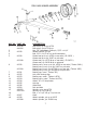
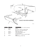
KEY NO. 1 2 3 PART NO. A30020 A3503 A4505 4 5 6 7 8 9 A2224 A30021 A2221 A3504 DESCRIPTION Shoulder pin, 1-1/4" to 1" NF w/ ctsk hole Bucket Pin, 1-1/4" x 2-3/8" w/ locking head Bolt, 5/8" x 1-1/4" NC w/ lock nut Right cutting edge, 4" Center cutting edge, 6" x 42" Left cutting edge, 4" Plow bolt, 1/2" x 1-3/4" w/ nut (12 req’d) Apron Grease fitting, 1/8" NPT std.
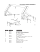
KEY NO. 1 2 3 4 5 6 7 PART NO. A3505 A4505 8 9 10 11 A30002 A2502 A3318 A30003 A3506 A3507 A3508 DESCRIPTION Actuating frame Pin, 1-1/4" x 2-3/8" w/ locking head Bolt, 5/8" x 1-1/2" NF w/ lock nut Pin, 1-1/2" x 5-3/4" Capscrew, 1/2" x 1" NC Pin, 1" x 5-5/8" Shoulder pin, 2-1/2" shoulder 1-1/4" to 1" NF Nut, 1" NFw/ nylon insert Roller Cotter pin, 1/4" x 2" Pin, 1-1/4" x 3-5/8" w/ sq.
MODEL A3516H1 KEY NO. 1 2 3 4 5 6 7 8 PART NO. A22H05 A22H06 A22H07 A22H08 A22H09 A22H10A A22H11 A3318 9 A2508 10 11 12 13 A22H12 A22H13 A22H14 A22H15 A22H15A A22H16 A22H18 A22H17 A22H19B 14 15 16 DESCRIPTION Piston nut, 3/4" NF Cast iron ring, 3-1/2" OD Back up washer, 3-1/2" OD O-ring seal, 3-1/2" OD x 3/16" Piston, 3-1/2" Piston gasket, 3/4" ID Shaft, 1-1/2" dia.
MODEL A2516H1 KEY NO. 1 2 3 4 5 6 7 8 PART NO. A22H05 A22H20 A22H21 A22H22 A22H23 A22H10A A22H24 A3318 9 A2508 10 11 12 A22H25 A22H26 A22H27 A22H27A A22H28 A22H29 A22H30B 13 14 DESCRIPTION Piston nut, 3/4" NF Cast iron piston ring, 2-1/2" OD Piston back up washer, 2-1/2" OD O-ring seal, 2-1/2" OD Piston, 2-1/2" Piston gasket Shaft, 1-1/4" dia.
Limited Warranty Statement Ashland Industries Inc. warrants each new product to be free from defects in material and workmanship. This warranty is applicable only for the normal service life expectancy of the product or components, not to exceed six consecutive months from the date of delivery of the new Ashland Industries product to the purchaser, or the date the product is first put into service via a rental agreement or other means, whichever occurs first.