
User Manual


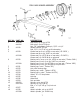
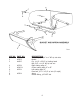

ASSEMBLY INSTRUCTIONS FOR MODEL 35 SCRAPER
1. A suitable hoist or lift should be available for assembly.
2. Pack wheel bearings with grease and install hubs to axle spindles.
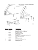
3. Raise actuating frame over bucket and lower into place so that the holes in the arms of the actuating frame
align with the rear hole on each side of the bucket. Insert 1 ¼ “ x 2-3/8” pin (with tab type head) from the
inside of the bucket. Secure with 5/8" x 1 ¼ “ NF bolt through bucket side with the locking nut to the outside.
4. Connect actuating arm bars into the front holes in the bucket. In doing so, be sure that the cast roller on the
opposite end of the actuating arm is in the up position and facing inward. Insert 1 ¼ “ x 2-3/8” pin (with tab
type head) from the inside of the bucket. Secure with 5/8" x 1 ¼ “ bolt through the bucket side with the lock nut
to the outside.
5. Connect a short chain from the cutting edge to the cross pipe of the actuating frame, then raise the bucket
and actuating frame assembly over the main frame and lower until the front of the actuating frame can be
connected to the 1 ½ “ ID bearing on each side of the main frame. Secure with 1 ½ “ x 5-5/8” pins on each
side. Lock these pins in place by turning the pin until the hole in the head aligns with the threaded hole in the
actuating frame, then secure with ½” x 1" NC capscrew and lockwasher.
6. Lift front end of actuating arm and connect to the brackets on the front frame cross-member using the 1 ¼ “
x 3-5/8” pins. Secure with ¼” x 2" cotter pin.
7. Raise the apron assembly over the scraper and lower into position so that the holes in the arms of the apron
align with the holes in the bucket sides. Insert the 1-1/4" to 1" shoulder pin through the apron arms and into the
bucket. Install lock nut inside the bucket and tighten securely.
8. Install hydraulic cylinders to main frame and actuating frame with rod end to actuating frame. Be sure the
grease hole in the rod end is facing up. Use 1" x 4 ¼” pin at the base of the cylinder. Secure with 3/16" x 1 ½”
cotter pins. Use 1" x 5-5/8" pin at the rod end of the cylinder. Secure with 1" x ½” NC capscrew and
lockwasher.
9. Install 3/8" 90° swivel adapters into front port on each cylinder. Tighten so that the hose connection faces the
rear.
10. Connect a 3/8" x 18" hose from the rear port of each cylinder to one of the pipe lines on the rear cross
frame. Be sure both hoses from the rear ports are connected to the same pipe line. Use a 3/8" straight adapter
at the pipe line.
11. Connect a 3/8" x 33" hose from the front port of each cylinder to the remaining pipe line on the rear cross
frame.
12. Raise rear of frame and install wheels to hubs. Also install wheels to front axle assembly on 35D model.
13. 35D: Raise front of frame and remove the two 5/8" x 4" bolts which hold the cast socket halves inside the
gooseneck. Remove the cast socket halves.
14. 35D: Roll the pole and axle assembly directly under the gooseneck and place the cast socket halves around
the ball swivel on axle. Lower the frame into place so that the socket halves seat into the gooseneck. (If
necessary, clamp halves together with C-clamp while inserting into gooseneck.) Replace 5/8" x 4" bolts and
tighten securely. Install long shank grease fitting into hole in back side of gooseneck.
15. Install all the grease fittings and grease liberally.
16. If available, place assembled scraper on level floor or pavement and measure the distance from the cutting
edge to floor, on both left and right sides, and then adjust axle spindle to obtain equal distance on both sides.
5