Models 450 & 500 PARTS MANUAL Version 4-04 Ashland Industries Inc. 1115 Rail Drive P.O. Box 717 Ashland, WI. 54806 Ph: 877-634-4622 Toll Free Ph: 715-682-4622 Fx: 715-682-9717 www.ashlandind.
Model 450 & 500 Scrapers HOW TO ORDER PARTS: IMPORTANT Parts must be ordered through your local authorized ASHLAND dealer. Be sure to state MODEL and SERIAL NUMBER of your machine, PART NUMBER, DESCRIPTION and QUANTITY needed. Unless this is done, we cannot provide prompt service or assure shipment of the correct parts. Ashland Industries weldable replacement parts are availabe to rebuild, modify or update your scraper to current factory specifications.
OPERATORS AND MAINTENANCE INSTRUCTIONS This scraper is a durable piece of equipment and with proper care will yield many years of trouble free operation. The scraper requires a power source with one 4-way (double acting) hydraulic control valve. After scraper has been assembled, it should be greased at all points where grease fittings are provided. Connect hydraulic hoses to tractor and operate the scraper to maximum raise and drop several times to force any air from the hydraulic lines and cylinders.
SAFETY SIGNAL WORDS Note the use of the signal words DANGER, WARNING and CAUTION with the safety messages. The appropriate signal word for each has been selected using the following guidelines: DANGER: Indicates an imminently hazardous situation that, if not avoided, will result in death or serious injury. This signal word is to be limited to the most extreme situations typically for machine components which, for functional purposes, cannot be guarded.
MODELS 450 & 500 SCRAPER ASSEMBLY INSTRUCTIONS 1. A suitable hoist or lift should be available for assembly. 2. Pack wheel bearing with grease and install hubs to rear spindles and front axle assembly. Be sure to follow the bearing numbers as shown in the parts listing as the front hubs require different bearings than the rear. 3. Raise actuating frame over bucket and lower into place so that the holes in the arms of the actuating frame aligns with the rear hole on each side of the bucket.
F. Install the cylinder with the two hose ports on the right side of the scraper with the rod end to the actuating frame, and the grease hole in the rod end bushing facing up. Use the same size pins as the cylinder on the left side. G. Install 3/8” NPT 90° swivel adapters in both ports of the cylinder. Tighten so that the swivel will be facing toward the rear. H. Connect a 3/8” x 18” hose from the forward pipe line on the frame cross-member to the base (rear) port of the cylinder (same as left cylinder). I.
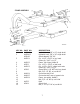
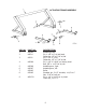
KEY NO. PART NO. 1 A450H01 2 A450H02 A22H03 3 A45001 4 5 6 A45002 A2502 A45003 7 8 9 10 11 12 13 14 15 A2206 A40004 A40005 A45004 A4523 A5004 DESCRIPTION Hydraulic hose, 3/8" x 18" single braid Hydraulic hose, 3/8" x 36" single braid Swivel adapter, 3/8" 90° Pin, 1-1/8" x 3-1/8" w/ sq. head Cotter pin, 3/16" x 1-1/2" Frame, four wheel, Model D Pin, 1-1/2" x 5-5/8" w/ tab head Pin, 1-1/8" x 3-1/4", cotter both ends Cotter pin, 3/16" x 1-1/2" Grease fiting, 1/8" NPT strt.
KEY NO. PART NO.
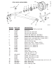
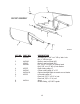
KEY NO. PART NO. 1 A45005 2 A4524 3 A2502 4 A45006 5 6 7 8 A45008 A45007 A30002 A30003 9 A6007A DESCRIPTION Actuating frame Pin, 1-1/8" x 6" w/ tab head Capscrew, 1/2" x 1" NC w/ LW Pin, 1-1/2" x 5-5/8" Capscrew, 1/2" x 1" NC w/ LW Pin, 1-1/4" x 2-9/16" w/ locking head Bolt, 5/8" x 1-1/2" NC w/ LW Actuating arm, right Actuating arm, left Roller Shoulder pin, 2-1/2" shoulder, 1-1/4" to 1" Nut, 1" NF w/ lock nut Pin, 1-1/4" x 4-1/8" w/ sq.
KEY NO. PART NO. 1 A30020 2 3 A45009 A5003 A45006 4 5 * 6 7 A2225 A45010 A45010-6 A2222 8 9 A45011 DESCRIPTION Shoulder pin, 1-1/4" to 1" NF w/ ctsk.
KEY NO. PART NO. 1 A45012 2 A60002 3 4 5 A2502 DESCRIPTION Frame section Pin, 1-1/8" x 3-5/8" w/ sq. head Cotter pin, 3/16" x 1-1/2" Grease fittings, 1/8" NPT strt. std.
* (Serial number break) KEY NO. 1 2 3 4 5 6 7 8 9 10 11 12 13 PART NO. A4512 A4513 A4514 A4515 A2233 A4516 *A4521A *A125047 A4519 A2235 A4520 A2239 DESCRIPTION Grease seal ( National 415082 ) Bearing cone, inner ( Timken 3784 ) Bearing cup, inner ( Timken 3720 ) Hub, less bearing cups Bearing cup, outer ( Timken 14276 ) Bearing cone, outer ( Timken 14137A ) Wheel, 20" D.C. (500 srs only: up to sn 20667, 12/02) Wheel, 22.5” x 8.
KEY NO. *1 *2 *3 *4 *5 *6 *7 *8 9 *10 *11 PART NO. DESCRIPTION A600H01 Valve stem plug A600H02 O-ring, seal A600H03 Spring A600H04 Ball valve A600H05 Valve seat sleeve A600H07 O-ring seal A600H08 Backup washer A600H06 O-ring seal A600H10 Valve housing A600H09A Plunger kit A600H11 Plug A600H12 Complete valve assembly * Parts sold in kit only, Kit No.
KEY NO. 1 2 3 4 5 6 7 8 9 10 11 PART NO. A600H22 A600H20 A600H18 A600H16 A600H14 A600H13 A600H15 A600H17 A600H19 A600H21 A600H23 A600H24 KEY NO. 1 2 3 DESCRIPTION Relief seat O-ring Ball Valve body gasket Adjusting screw O-ring Jam nut Acorn cap Adjusting screw Valve body Spring Relief seat Valve housing Complete valve assembly PART NO.
KEY NO. 1 2 3 4 5 6 7 8 9 10 PART NO. A300H03 A300H04 A300H05 A300H06 A300H07 A45H05 A45H03 A4524 11 12 13 14 A45H04 A300H11 A300H12 A22H15 A22H15A A300H13 A22H18 A22H17 A300H14B 15 16 17 A45003 DESCRIPTION Piston nut, 1" NF Cast iron ring, 4" OD Backup washer, 4" OD O-ring seal, 4" OD x 3/16" Piston, 4" Piston gasket, 1" Shaft, 1-1/2" dia.
KEY NO. 1 2 3 4 5 6 7 8 9 PART NO. A300H03 A300H04 A450H15 A300H06 A45H05 A45H03 A4524 10 11 12 13 A450H10 A300H11 A300H12 A22H15 A22H15A A300H13 A22H18 A22H17 A450H11B 14 15 16 A45003 DESCRIPTION Piston nut, 1" NF Cast iron ring, 4" OD Piston, 4" O-ring seal, 4" OD, x 3/16" Piston gasket, 1" Shaft, 1-1/2" dia.
KEY NO. 1 2 3 4 5 6 7 8 PART NO. A300H03 A300H04 A300H05 A300H06 A300H07 A45H05 A600H32 A60002 9 A45001 10 11 12 13 A600H33 A300H11 A300H12 A22H15 A22H15A A300H13 A22H17 A222H18 A300H14B 14 15 16 DESCRIPTION Piston nut, 1" NF Cast iron ring, 4" OD Backup washer, 4" OD O-ring seal, 4" OD x 3/16" Piston, 4" OD Piston gasket, 1" Shaft, 1-1/2" Pin, 1-1/8" x 3-1/2" w/ sq. head Cotter pin, 3/16" x 1-1/2" Pin, 1-1/8" x 3-1/4" w/ sq.
PLUMBING ASSEMBLY PIPE AND FITTINGS KEY # DESCRIPTION LENGTH 1 1/2" STD Black Pipe 90-1/4 2 1/2" STD Black Pipe 86-1/2 3 1/2" STD Black Pipe 34-1/2 4 1/2" STD Black Pipe 27-3/4 5 1/2" STD Black Pipe 37-1/2 6 1/2" STD Black Pipe 31-1/2 7 1/2" STD Black Pipe 90 8 1/2" STD Black Pipe 39-3/4 9 1/2" STD Black Pipe 45-3/4 10 1/2" STD Black Pipe 3 11 1/2" NPT Close nipple 12 1/2" NPT x 90° elbow 13 1/2" NPT x 45° elbow 14 1/2" NPT x 90° st.
KEY NO. 1 2 3 4 5 6 7 8 9 10 11 12 13 QTY. 1 1 1 2 1 1 1 1 1 1 1 1 1 1 PART NO.
Limited Warranty Statement Ashland Industries Inc. warrants each new product to be free from defects in material and workmanship. This warranty is applicable only for the normal service life expectancy of the product or components, not to exceed six consecutive months from the date of delivery of the new Ashland Industries product to the purchaser, or the date the product is first put into service via a rental agreement or other means, whichever occurs first.