
Manual

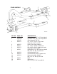
F. Install the cylinder with the two hose ports on the right side of the scraper with the rod end
to the actuating frame, and the grease hole in the rod end bushing facing up. Use the same
size pins as the cylinder on the left side.
G. Install 3/8” NPT 90° swivel adapters in both ports of the cylinder. Tighten so that the
swivel will be facing toward the rear.
H. Connect a 3/8” x 18” hose from the forward pipe line on the frame cross-member to the
base (rear) port of the cylinder (same as left cylinder).
I. Connect a ½” x 36” hose from the remaining pipe line on the frame cross-member to the
forward port of the cylinder.
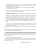
J. Install the 4” x 8” hydraulic cylinder on the rear of the scraper with the rod end connected
to the rear frame section with the grease hole facing up. Insert the 1-1/8” x 3-1/8” square
head pin at the base of the cylinder. Secure with 3/16” x 1 ½” cotter pin. Use 1-1/8” x 3 ½”
square head pin at the rod end of the cylinder and secure with a 3/16” x 1 ½” cotter pin.
K. Install 3/8” NPT male x ½” NPT female 90° swivel adapters in the two ports of the rear
cylinder. Tighten so the swivels face toward each other and somewhat to the left of the
scraper.
L. Install one ½” x 24” hose form the lower elbow of the single line lock valve to the base port
of the cylinder. Install the remaining ½” x 24” hose form the upper elbow of the lock valve to
the rod end port of the cylinder.
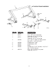
9. Raise the rear of the frame and install wheels to hubs. Also install wheels to front axle assem-
bly.
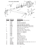
10. Raise front of frame and remove the two 5/8” x 4” bolts which hold the cast socket halves
inside the gooseneck. Remove the cast socket halves.
11. Roll the pole and axle assembly directly under the gooseneck, place the cast socket halves
around the ball socket on the axle. Lower the frame into place so that the socket halves seat into
the gooseneck. (If necessary, clamp halves together with C-clamp while inserting into gooseneck).
Replace 5/8” x 4” bolts and tighten securely. Install long shank grease fitting into the hole in the
back side of gooseneck.
12. Install all the grease fittings and grease liberally.
13. If available, place assembled scraper on level floor or pavement and measure the distance
from the cutting edge to floor, on both left and right sides, and then adjust axle spindle to obtain
equal distance on both sides.
ASHLAND INDUSTRIES, INC.
6